

Parallel external fixator and application method thereof
An external fixator and parallel technology, which is applied in the field of bone treatment devices, can solve problems such as soft tissue and neurovascular secondary injuries
- Summary
- Abstract
- Description
- Claims
- Application Information
AI Technical Summary
Problems solved by technology
Method used
Image

Examples
Embodiment 1
[0134] A parallel-type external fixator in this embodiment includes a frame part and a supporting computer software part.
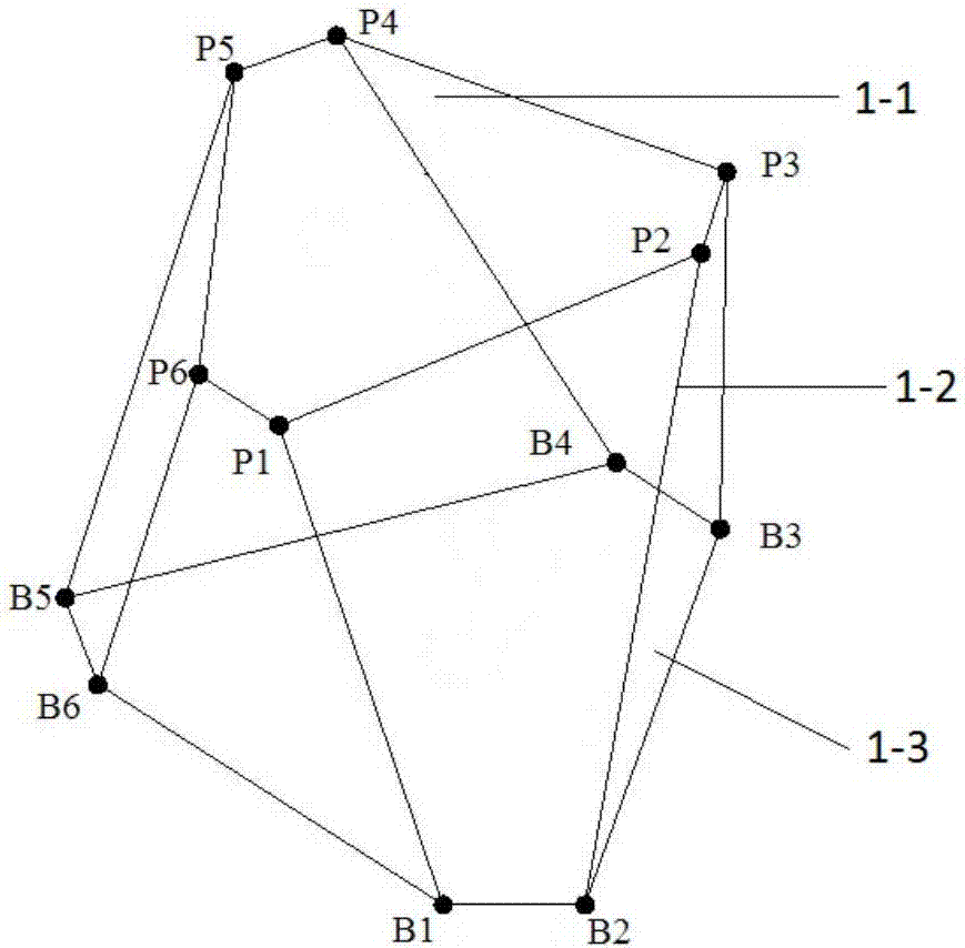
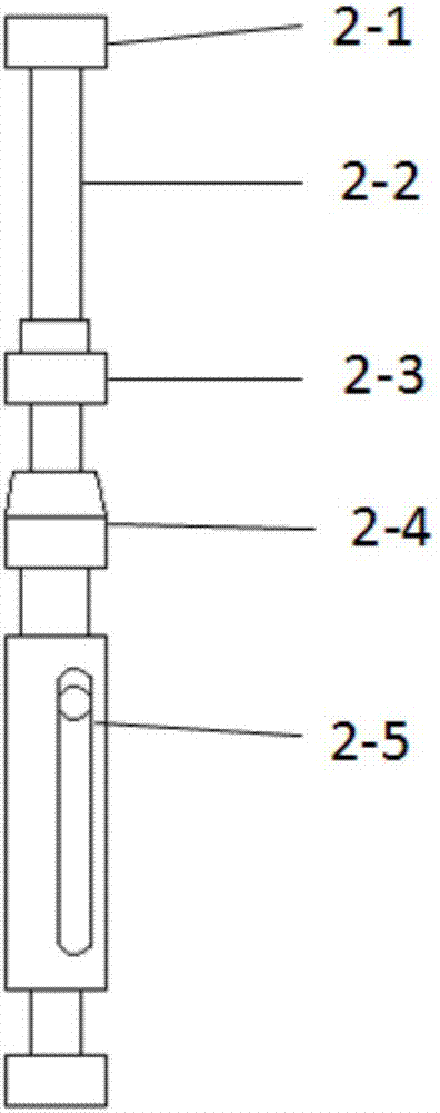
[0135] The frame part of this parallel type external fixator is composed of a reference ring 1-1, a moving ring 1-3 and six driving rods 1-2, and the reference ring 1-1 and the moving ring 1-3 are connected by a universal joint The device 2-1 is connected with six driving rods 1-2, and the six driving rods 1-2 connecting the moving ring 1-3 and the reference ring 1-1 are arranged in parallel, and the mathematical model of the frame part is as follows figure 1 Example shown. The inner diameter of the reference ring 1-1 is divided into eight types: 90mm, 110mm, 130mm, 150mm, 170mm, 190mm, 210mm and 230mm; the inner diameter of the moving ring 1-3 is also divided into eight types corresponding to the inner diameter of the reference ring 1-1: 90mm, 110mm, 130mm, 150mm, 170mm, 190mm, 210mm and 230mm. The structure of the driving rod 1-2 is as figure 2 In t...
Embodiment 2
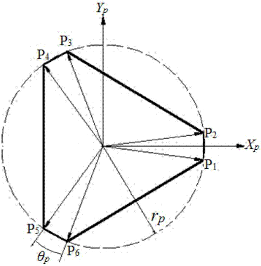
[0139] See Figure 3, Figure 4 , Fig. 5 and Fig. 6, the present embodiment provides a kind of application method of parallel type external fixator, it realizes based on a kind of parallel type external fixator of embodiment 1, specific steps are as follows:
[0140] The first step is to install a parallel external fixator on fracture patients who need surgery:
[0141] (1.1) First, select the reference ring 1-1 and the moving ring 1-3 according to the body shape of the fracture patient, and determine the driving rod with the corresponding rod length according to the selected reference ring 1-1 and the moving ring 1-3;
[0142] (1.2) Design the bone segment deformity model. In the bone segment deformity model, the fracture segment is divided into a reference bone segment and a moving bone segment. That is, the doctor selects the proximal or distal end of the fracture reference fracture as the reference bone segment, and the other end is To move the bone segment, the selection of...
PUM
| Property | Measurement | Unit |
|---|---|---|
| The inside diameter of | aaaaa | aaaaa |
| Length | aaaaa | aaaaa |
Abstract
Description
Claims
Application Information