Biomass power plant flue gas purification treatment process and system based on dry-process desulfurization and low-temperature denitration

A dry desulfurization and low-temperature denitrification technology, which is applied in the field of desulfurization, denitrification and dust removal process and system, can solve problems such as difficult to ensure denitrification efficiency, pollution, SCR catalyst wear, etc., and achieve the effect of improving denitrification stability, simple process and easy maintenance

Pending Publication Date: 2017-06-20
SHANGHAI ELECTROMECHANICAL DESIGN & RES INST CO LTD
View PDF7 Cites 25 Cited by
  • Summary
  • Abstract
  • Description
  • Claims
  • Application Information

AI Technical Summary

Problems solved by technology

[0006] 1. If the SCR process is adopted, referring to the high-dust layout of the current mainstream process of coal-fired power plants, due to the high content of flue gas dust and alkali metals (Na, K) in biomass power plants, the SCR catalyst will be worn, blocked, or polluted , poisoning, thus greatly reducing the service life of the catalyst
[0007] 2. If the SNCR process is adopted, since the furnace temperature of the biomass circulating fluidized bed boiler is low (<750°C), it is not within the SNCR denitrification temperature window (850°C-1100°C), so it is difficult to guarantee the denitrification efficiency

Method used


Image

  • Biomass power plant flue gas purification treatment process and system based on dry-process desulfurization and low-temperature denitration
  • Biomass power plant flue gas purification treatment process and system based on dry-process desulfurization and low-temperature denitration

Examples


Embodiment Construction

[0046] The present invention will be further described below in conjunction with the accompanying drawings and specific embodiments.

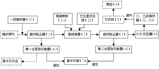
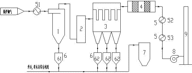
[0047] see figure 1 with figure 2 , a dry desulfurization and low-temperature denitrification biomass power plant flue gas purification treatment system, including a cyclone dust collector 1, a desulfurization device 2, a bag filter 3, an SCR system 4, a heat exchanger 5, and a bin pump pneumatic ash removal device 6. Centralized ash storage 7, induced draft fan 8, chimney 9;

[0048] The air inlet of the cyclone dust collector 1 is connected to the dust-containing flue gas produced by burning biomass in the boiler, the exhaust port of the cyclone dust collector 1 is connected to the air inlet of the desulfurization device 2 through the pipeline, and the exhaust port of the desulfurization device 2 is connected to the bag through the pipeline Type dust collector 3 air inlets. A primary heat exchanger 51 is installed in front of the air inle...


PUM


Abstract

The invention relates to a biomass power plant flue gas purification treatment process and system based on dry-process desulfurization and low-temperature denitration (low-temperature SCR (Selective Catalytic Reduction)). The biomass power plant flue gas purification treatment process based on the dry-process desulfurization and the low-temperature denitration comprises the following steps: firstly, carrying out primary dust removal on dust-containing flue gas generated by combusting biomasses in a boiler, and keeping temperature of gas which is pre-treated by a cyclone dust collector (1) at about 215 DEG C; secondly, carrying out dry-process desulfurization purification treatment on the flue gas, which is subjected to the primary dust removal, in a desulfurization device (2); thirdly, treating the desulfurized flue gas by adopting a bag type dust collector (3); fourthly, conveying the gas into an SCR system (4) and carrying out denitration reaction to generate harmless nitrogen gas and steam; after recycling residual heat through a heat exchanger (5) and conveying the gas into a chimney (9) through a draught fan (8) and discharging to the atmosphere; fifthly, inputting smoke ash separated from the cyclone dust collector and the bag type dust collector into a concentrated ash silo (7) through a first bin pump pneumatic ash removal device (61) and a second bin pump pneumatic ash removal device (62) and storing.

Description

technical field [0001] The invention relates to a desulfurization, denitrification and dust removal process and system for biomass power generation, in particular to a biomass power plant flue gas purification process and system based on dry desulfurization and low-temperature denitrification (low-temperature SCR). Background technique [0002] Biomass power generation mainly uses agricultural and forestry waste as fuel to generate electricity through direct combustion. Biomass direct combustion power generation is to send biomass raw materials into a specific boiler for combustion to generate steam, which drives a turbine generator to generate electricity. In recent years, combined with my country's traditional agricultural and forestry waste disposal situation, and the concept of environmental protection has been deeply rooted in the hearts of the people, the level of environmental protection technology and equipment has been improved, and the state has launched a series o...

Claims


Application Information

Patent Timeline
Patent Type & Authority Applications(China)
IPC IPC(8): B01D50/00B01D53/50B01D53/75B01D53/83B01D53/86B01D53/56B01D53/64
CPCB01D53/508B01D53/64B01D53/75B01D53/83B01D53/8631B01D2251/60B01D2255/20707B01D2255/20723B01D50/20
Inventor 蔡韵杰何佳杨富强惠文博晏金炜
Owner SHANGHAI ELECTROMECHANICAL DESIGN & RES INST CO LTD
Why Eureka
Try Eureka