Floor board tightly attached mounting method

An installation method and floor slab technology are applied in the directions of construction, building structure, and building material processing, etc., which can solve the problem that the floor slab and the platform steel beam are not tightly attached, which affects the structural accuracy and service life, and cannot guarantee the floor slab pressure at the same time. The problem of tightness and other problems can be achieved to facilitate the operation of aerial work, reduce the phenomenon of arching and light weight

Active Publication Date: 2017-06-20
CHINA FIRST METALLURGICAL GROUP
View PDF6 Cites 0 Cited by
  • Summary
  • Abstract
  • Description
  • Claims
  • Application Information

AI Technical Summary

Problems solved by technology

In steel structure buildings, the floor slab is generally used as the roof slab of the factory roof or the floor slab of the floor. When installing the floor slab, the floor slab is generally lapped with the platform steel beam first, and then fixed by welding nails ( The welding studs are located in the top recess of the floor slab), but due to various factors, the floor slab and the platform steel beam are always not tightly attached at the overlap, so after welding the welding studs with a welding torch, there will be an arching phenomenon, which will affect the structure. Accuracy and service life
Patent CN201620005767.8 provides a "floor slab back pressure auxiliary device". The nailed floor plate is pressed tightly, and the welding stud welding machine can start to weld the welding stud at the floor plate. This device has realized the close installation, but there are the following problems: 1) The device needs to be adjusted according to the processing sequence of the welding stud. Move sequentially, and each time you move, you need to adjust the position of the device, which is not conducive to high-altitude operations; 2) the device can only ensure that the next floor plate to be welded is compressed, and cannot ensure that all floor plates are compressed at the same time. In the past, it was necessary to adjust the position of the device, and all the welding studs could not be processed in sequence without interruption, and the efficiency was low

Method used


Image

  • Floor board tightly attached mounting method
  • Floor board tightly attached mounting method
  • Floor board tightly attached mounting method

Examples


Embodiment Construction

[0016] The present invention will be further described below in conjunction with the accompanying drawings and embodiments.

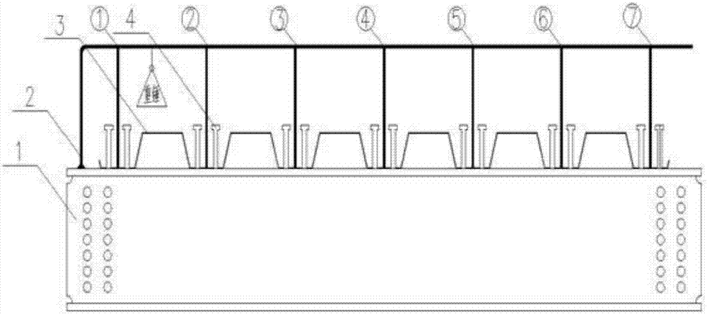
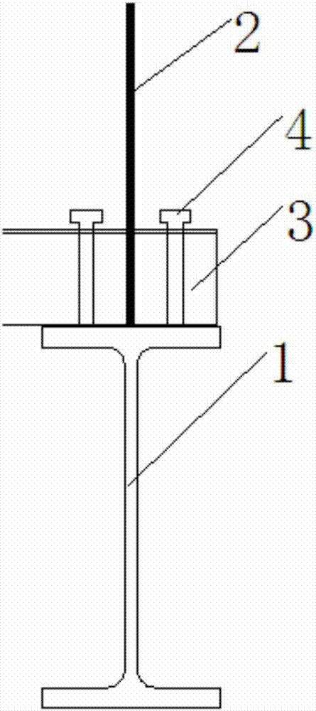
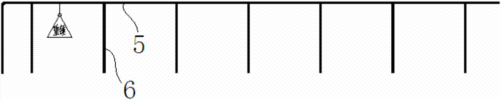
[0017] Such as figure 1 As shown, a floor slab close installation method provides a component 2 at the overlap between the floor slab 3 and the platform steel beam 1. The component 2 includes a cross bar 5 located above the floor slab 3 and distributed and fixed along the cross bar 5. Vertical rod 6, the bottom end of the vertical rod 6 at one end of the cross bar 5 is vertically fixed on the top surface of the platform steel beam 1, and the bottom ends of the remaining vertical rods 6 are vertically supported on the top surface of the floor plate 3 in turn. , and then fix all the welding studs 4 in turn, and finally remove the member 2.

[0018] In the present invention, after the components 2 are installed, all the floor slabs 3 are tightened, and all the welding studs 4 can be fixed in turn. When the welding studs 4 are fixed, the vibration generate...


PUM


Abstract

The invention relates to a floor board tightly attached mounting method. The floor board tightly attached mounting method comprises the steps that a component is provided at the lap joint of a floor board and a platform steel beam and comprises a cross rod located above the floor board and vertical rods distributed and fixed along the cross rod; the bottom end of the vertical rod located at one end of the cross rod is perpendicularly fixed to the top face of the platform steel beam, and the other vertical rods are perpendicularly jacked at a concave position of the top face of the floor board in sequence; then all welded studs are sequentially fixed; and finally, the component is dismantled. By adoption of the floor board tightly attached mounting method, the position of the component does not need to be adjusted, aloft operation is facilitated, efficiency is high, and recyclability is achieved.

Description

technical field [0001] The invention belongs to the technical field of steel structure installation, and in particular relates to a method for close installation of floor boards. Background technique [0002] Compared with the traditional reinforced concrete structure, the steel structure has the advantages of homogeneity, high strength, fast construction speed, good earthquake resistance and high recovery rate, so it is more and more widely used. In steel structure buildings, the floor slab is generally used as the roof slab of the factory roof or the floor slab of the floor. When installing the floor slab, the floor slab is generally lapped with the platform steel beam first, and then fixed by welding nails ( The welding studs are located in the top recess of the floor slab), but due to various factors, the floor slab and the platform steel beam are always not tightly attached at the overlap, so after welding the welding studs with a welding torch, there will be an arching...

Claims


Application Information

Patent Timeline
Patent Type & Authority Applications(China)
IPC IPC(8): E04G21/18
CPCE04G21/1841
Inventor 朱华民单明吴梦先胡胜奎
Owner CHINA FIRST METALLURGICAL GROUP
Why Eureka
Try Eureka