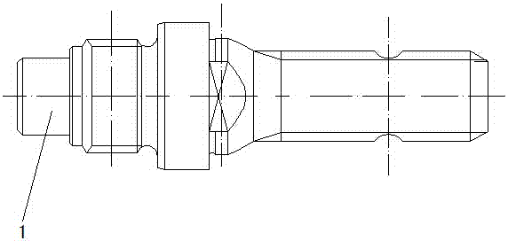
Power output shaft of tractor and machining method of shaft
A technology of power output shaft and processing method, which is applied in the field of mechanical equipment, can solve the problems of increased operation cost, long replacement cycle, high cost of power output shaft, etc., and achieve the effects of cost reduction, improvement of utilization efficiency, and reduction of repair cycle
- Summary
- Abstract
- Description
- Claims
- Application Information
AI Technical Summary
Problems solved by technology
Method used
Image


Examples
Embodiment 1
[0022] Example 1: The shaft body 1 after rough turning is subjected to overall quenching and tempering treatment, the quenching heating time is 1.5h, the quenching temperature is 850°C, and then the oil is cooled to 230°C, and then high-temperature tempering treatment is performed, and the high-temperature tempering temperature is 560°C ℃, the high-temperature tempering time is 2.5-3 hours, after high-temperature tempering, carry out normal-temperature oil cooling to room temperature, so that the surface hardness of the shaft body reaches HBS270-280;
[0023] ③Finish turning process, except for the dense tooth spline part 1-1 of the head of the shaft body 1, the rest are all processed and formed;
[0024] ④ Part of the dense tooth spline 1-1 at the head of the shaft body 1 is treated with high-frequency 80kw partial annealing, the processing frequency is 10000Hz, the heating time is 9-11min, the heating temperature is 600-800°C, and the annealing temperature is 600-800°C , the...
Embodiment 2
[0025] Example 2: The head part of the shaft body 1, the dense tooth spline 1-1, is treated with high-frequency 80kw local annealing, the processing frequency is 10000Hz, the heating time is 10min, the heating temperature is 700°C, the annealing temperature is 700°C, and the annealing time is 700°C. It is 10min, then extruded with the molding die;
[0026] ⑤ After the machining of the shaft body 1 is completed, the whole body is quenched. The quenching heating time is 1-2 hours, and the quenching temperature is 800-900 ° C. Then, it is cooled to room temperature with normal temperature oil, so that the surface hardness of the shaft body 1 reaches HRC50-54;
Embodiment 3
[0027] Example 3: After the shaft body 1 is machined, it is quenched as a whole. The quenching heating time is 1.5 hours, and the quenching temperature is 850°C. Then, it is cooled to room temperature with normal temperature oil, so that the surface hardness of the shaft body 1 reaches HRC50-54;
[0028] ⑥ Shaft body 1 is subjected to artificial 48h aging treatment at a temperature of 150-250°C to remove surface stress.
PUM
| Property | Measurement | Unit |
|---|---|---|
| Surface hardness | aaaaa | aaaaa |
| Surface hardness | aaaaa | aaaaa |
Abstract
Description
Claims
Application Information
 - R&D
- Intellectual Property
- Life Sciences
- Materials
- Tech Scout
- Unparalleled Data Quality
- Higher Quality Content
- 60% Fewer Hallucinations
Browse by: Latest US Patents, China's latest patents, Technical Efficacy Thesaurus, Application Domain, Technology Topic, Popular Technical Reports.
© 2025 PatSnap. All rights reserved.Legal|Privacy policy|Modern Slavery Act Transparency Statement|Sitemap|About US| Contact US: help@patsnap.com