Device and method for centering assembling adjustment of large-calibre aspheric-surface reflector

A technology of plane mirrors and mirrors, which is applied in installation, optics, instruments, etc., can solve the problems of spot receiving angle, limited dial indicator measurement accuracy, and difficulty in erection, so as to improve the accuracy of measurement and installation and reduce the Adjustment and technical risk, and the effect of expanding the applicable scope of measurement

Active Publication Date: 2017-06-20
西安应用光学研究所
View PDF6 Cites 19 Cited by
  • Summary
  • Abstract
  • Description
  • Claims
  • Application Information

AI Technical Summary

Problems solved by technology

[0004] 1. Method 1 can only find the image of the center of the sphere, but cannot locate the vertex image of the surface, so what is adjusted is not the real optical axis of the aspheric surface, that is, the axis of rotational symmetry;
[0005] 2. Method 1 will also calibrate the axis of symmetry by locating the centers of curvature of two different rings (regions) on the aspheric surface. In this method, since the curvature difference between the rings of the aspheric surface is not large, each center of curvature The axial positions are very close to each other, resulting in very low centering accuracy, which cannot reach the arc-second level
[0006] 3. Method 2 is limited by the measurement accuracy of the dial indicator, and the measurement error introduced is relatively large; and this method is a contact measurement method, which has certain damage to the aspheric surface element
[0007] In the article "Determination of the Optical Axis of Parabolic Mirrors" published in "Applied Optics" in March 2008, a method for determining the optical axis of parabolic mirrors by using incident parallel beams was introduced. When the mirror rotates, the actual normal changes of each point in the incident area are not the same, so it is difficult to obtain a spot pattern with a complete motion track on the CCD; and for different DUTs, the incident and reflection directions are random, and the CCD receiving device The placement position is not fixed, and it is very difficult to realize; at the same time, the tested sample adopts the vertical side-hanging installation method, and there is a large technical risk for large-diameter components
In the same year, the utility model patent "An Aspheric Lens Eccentricity Measuring Device", publication number: CN201096611Y, is the same author as the above-mentioned paper, and its invention content is compared with the method described in the paper, changing the incidence of wide beam to laser The beam is incident, but there are the same problem of spot receiving angle and safety problem, which is difficult to realize in actual operation
[0008] In the article "Research on Aspheric Interferometric Centering Method" published in "Acta Photonica Sinica" in July 2008, a method of using the principle of interferometry to judge the eccentricity error by observing the change of the interference pattern is proposed. This method is greatly affected by environmental vibration. , the actual measurement results are not necessarily accurate, and the introduction of an interferometer, the entire experimental device has a large structure and is difficult to erect, which cannot meet the actual needs of trial production and batch production.

Method used


Image

  • Device and method for centering assembling adjustment of large-calibre aspheric-surface reflector
  • Device and method for centering assembling adjustment of large-calibre aspheric-surface reflector
  • Device and method for centering assembling adjustment of large-calibre aspheric-surface reflector

Examples


Embodiment Construction

[0039] Describe the present invention below in conjunction with specific embodiment:

[0040] In view of the problems existing in the existing centering and adjusting technology of large-diameter aspheric mirrors, in order to realize the centering and adjusting of aspheric mirrors, this embodiment provides a device with reasonable structure and easy operation, and a high-speed Accurate, efficient method.

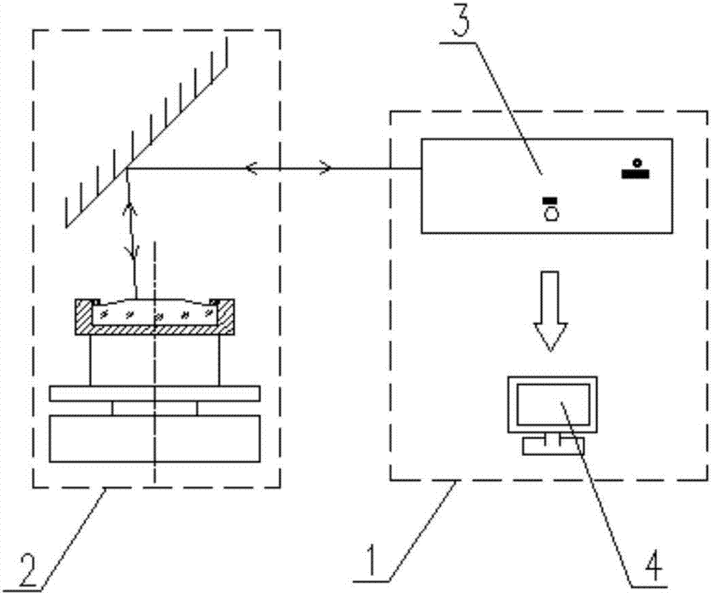
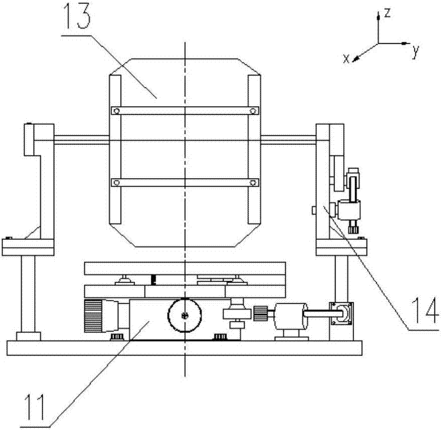
[0041] Such as figure 1 As shown, the aspheric mirror centering and adjusting device is composed of an eccentricity measurement system 1 and a rotary adjustment mechanism 2 .

[0042]The eccentricity measurement system 1 includes a laser emitting and receiving subsystem 3, an image display and processing subsystem 4;

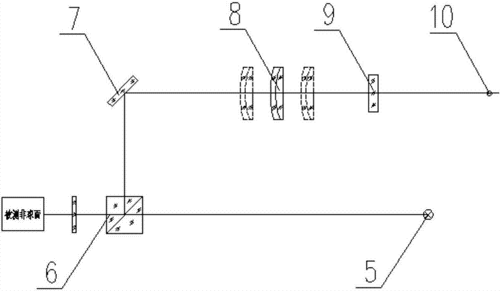
[0043] The laser emitting and receiving sub-system 3 includes a red light semiconductor laser 5, a beam splitting cube 6, a reflector 7, an adjustable laser receiving objective lens 8, an attenuation sheet 9 and a CCD10; Optical axis parallel difference is ...


PUM


Abstract

The invention, which belongs to the technical field of optical machine assembling adjustment, discloses a device and method for centering mounting adjustment of a large-calibre aspheric-surface reflector. The method is characterized in that a to-be-adjusted aspheric-surface reflector is fixed at a rotary adjusting mechanism of a centering device; deviation between an optical axis of the aspheric-surface reflector and a reference axis is measured in real time by using an eccentricity measuring system in the device and the position and direction of the deviation are displayed at a display device; and the position attitude of the aspheric-surface reflector is adjusted, so that the overlapping error between the reflector optical axis and the reference axis is smaller than a designed allowance value and thus centering assembling adjustment of the aspheric-surface reflector is completed. With the device and method, a centering problem of a large-calibre rotary symmetric aspheric-surface reflector can be solved. The device and method have characteristics of simple instrument erecting, great convenience in operation, and high centering precision and the like.

Description

technical field [0001] The invention belongs to the technical field of optical-mechanical assembly and adjustment, and in particular relates to a device and method for centering and adjusting large-diameter aspheric mirrors. Background technique [0002] Under the background of information-based warfare, weapons and equipment require optical imaging and stabilized aiming systems to have a wider spectral range and a longer operating distance. Therefore, the design utilization rate of large-aperture aspheric mirrors is getting higher and higher. Compared with the traditional spherical transmission system, the optical system using aspheric mirrors has a more obvious impact on the image quality from the center deviation, which needs to be strictly controlled during the assembly and adjustment stage. Different from spherical optical elements, aspheric mirrors have "uniqueness of optical axis", and their optical axis is the symmetry axis of the aspheric surface. If there is a devi...

Claims


Application Information

Patent Timeline
Patent Type & Authority Applications(China)
IPC IPC(8): G02B7/182G02B7/183G02B7/198
CPCG02B7/1822G02B7/183G02B7/198
Inventor 左晓舟惠刚阳王娇颖张燕张云龙王中强
Owner 西安应用光学研究所
Why Eureka
Try Eureka