Magnetic tunnel junction and magnetic device and electronic equipment comprising same

A technology of magnetic tunnel junction and electronic device, applied in the field of spintronics, which can solve the problems of complex operation, consumption, high density of magnetic tunnel junction, etc.

Active Publication Date: 2017-06-20
INST OF PHYSICS - CHINESE ACAD OF SCI
View PDF3 Cites 22 Cited by
  • Summary
  • Abstract
  • Description
  • Claims
  • Application Information

AI Technical Summary

Problems solved by technology

E.g, Figure 1A and 1C The flipping scheme still needs to apply an external magnetic field, resulting in high power consumption and complicated operation, and the external magnetic field may affect adjacent devices, causing stability problems
for Figure 1B Although the scheme shown does not require an external magnetic field, its flipping speed is low, so it is not suitable for high-speed oper

Method used


Image

  • Magnetic tunnel junction and magnetic device and electronic equipment comprising same
  • Magnetic tunnel junction and magnetic device and electronic equipment comprising same
  • Magnetic tunnel junction and magnetic device and electronic equipment comprising same

Examples


Embodiment Construction

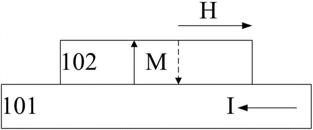
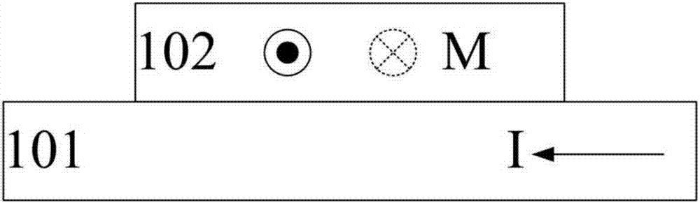
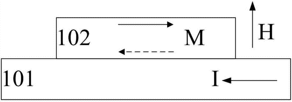
[0025] figure 2 is a schematic diagram illustrating a flipping scheme according to an embodiment of the present invention. Such as figure 2 As shown, the first magnetic layer 210 and the second magnetic layer 230 can be separated by a spin Hall effect SHE layer 220, wherein the magnetic anisotropy directions of the first magnetic layer 210 and the second magnetic layer 230 are perpendicular to each other, for example ,Such as figure 2 As shown by the arrow in , the first magnetic layer 210 may have in-plane magnetic anisotropy, and the second magnetic layer 230 may have perpendicular magnetic anisotropy, or vice versa.

[0026] The SHE layer 220 may be formed of a conductor material having strong spin-orbit coupling properties. When current flows through a conductive material with strong spin-orbit coupling properties, due to the spin Hall effect, a spin-polarized current can be formed on the surface of the conductive material, thereby imparting spin to the adjacent magn...


PUM


Abstract

The invention relates to a magnetic tunnel junction and a magnetic device comparing the same. According to one embodiment, the magnetic tunnel junction can comprises a reference magnetic layer, a spacing layer and a composite free magnetic layer, wherein the spacing layer is arranged on the reference magnetic layer, the composite free magnetic layer is arranged on the spacing layer and comprises a first free magnetic layer, a spinning Hall effect (SHE) layer and a second bias magnetic layer, the first free magnetic layer is arranged at one side of the spacing layer, the SHE layer is arranged on the first free magnetic layer, the second bias magnetic layer is arranged on the SHE layer, ferromagnetic coupling or anti-ferromagnetic coupling between the first free magnetic layer and the second bias magnetic layer is induced by the SHE layer, one of the first free magnetic layer and the second bias magnetic layer has in-plane magnetic anisotropy, the other one of the first free magnetic layer and the second bias magnetic layer has vertical magnetic anisotropy, and the magnetic anisotropy of the second bias magnetic layer is larger than the magnetic anisotropy of the first free magnetic layer.

Description

technical field [0001] The present invention relates generally to spintronics, and more particularly, to a magnetic tunnel junction that enables pure current drive without the need for an applied external magnetic field, and to magnetic devices comprising such a magnetic tunnel junction, such as Magnetic random access memory and spin logic devices, etc., and electronic equipment including such magnetic devices. Background technique [0002] Magnetic tunnel junction (MTJ) has a wide range of applications, such as in magnetic memory, spin logic devices, magnetic sensors, etc., and thus is one of the important magnetic components that has been intensively studied. The magnetic tunnel junction generally includes a free magnetic layer, a reference magnetic layer and a tunneling barrier layer between them. The magnetic moment of the free magnetic layer can be flipped freely, while the magnetic moment of the reference magnetic layer is fixed. The tunnel barrier layer is formed of ...

Claims


Application Information

Patent Timeline
IPC IPC(8): H01L43/08G11C11/16
CPCG11C11/161H10N50/10
Inventor 韩秀峰万蔡华张轩
Owner INST OF PHYSICS - CHINESE ACAD OF SCI
Why Eureka
Try Eureka