Permanent-magnet wind power generation system grid synchronization method

A wind power generation system and synchronization technology, applied in wind power generation, electrical components, circuit devices, etc., can solve problems such as grid voltage asymmetry and distortion interference

Inactive Publication Date: 2017-06-20
姚秋丽
View PDF0 Cites 1 Cited by
  • Summary
  • Abstract
  • Description
  • Claims
  • Application Information

AI Technical Summary

Problems solved by technology

[0005] In order to overcome the problem that the grid voltage synchronization signal is susceptible to interference from grid voltage a

Method used


Image

  • Permanent-magnet wind power generation system grid synchronization method
  • Permanent-magnet wind power generation system grid synchronization method
  • Permanent-magnet wind power generation system grid synchronization method

Examples


Embodiment Construction

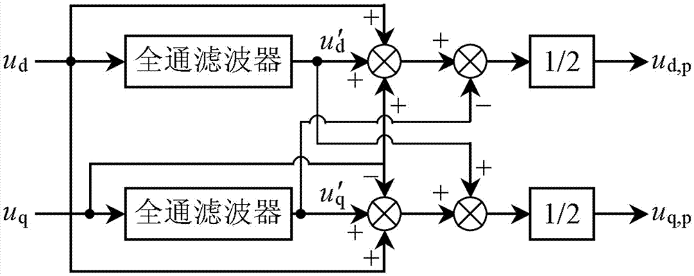
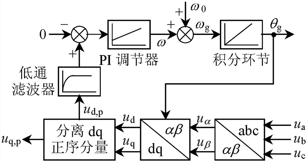
[0015] see figure 1 , three-phase asymmetrical voltage u a , u b , u c It can be decomposed into positive sequence components and negative sequence components by using the symmetrical component method. The space voltage phasor is decomposed into two rotating phasors: the positive sequence voltage phasor rotating with w and the negative sequence voltage phasor rotating with -w. Using phase-locked loop algorithm and selecting appropriate parameters can achieve θg=wt. Therefore the voltage u can be written d and u q . When the power grid is asymmetrical, due to the influence of negative sequence voltage u d and u q Both produced a 2w harmonic component. In order to eliminate harmonic components, an all-pass filter is added to the phase-locked loop to generate a phase-shifted u of π / 2 d and u q . The cutoff frequency of the all-pass filter is set to 2w. figure 2 in, for u d and u q Appropriate addition and subtraction were performed to separate u in positive sequen...


PUM


Abstract

A permanent-magnet wind power generation system grid synchronization method comprises three parts: voltage positive sequence component separation, a novel phase-locked loop and network-side converter control. The novel phase-locked loop used in the invention is a new method for separating the positive sequence components of the asymmetric grid voltage under the double synchronous rotational coordinates by using an all-pass filter and the mathematical operation and then extracting phases. The novel phase-locked loop is suitable for use in the grid synchronization of a direct-drive permanent-magnet wind power generation system, and has better performance in the case of unbalanced input voltage.

Description

technical field [0001] The invention relates to a permanent magnet wind power generation system, in particular to a method for synchronizing a power grid of the permanent magnet wind power generation system. Background technique [0002] The high-power direct-drive permanent magnet wind power generation system is one of the most practical wind power generation systems at present, but the grid voltage synchronization signal of the grid-side converter in this system is easily disturbed by the grid voltage asymmetry and distortion, so the power grid Synchronization is a difficult point in grid-side converter control. At present, the research on the direct-drive permanent magnet wind power generation system mainly focuses on the control strategy of the converter system. [0003] At present, the common methods are: direct-drive permanent magnet wind power generation system pitch angle and generator speed control strategy; aiming at the instability brought by the LCL filter to th...

Claims


Application Information

Patent Timeline
IPC IPC(8): H02J3/40
CPCH02J3/386H02J3/40Y02E10/76
Inventor 姚秋丽
Owner 姚秋丽
Why Eureka
Try Eureka