Asymmetrical half-bridge converter topological structure

A technology of half-bridge converter and topology structure, which is applied in the direction of converting DC power input to DC power output, instruments, and adjusting electrical variables. It can solve the problems of harsh conditions and the inability to realize soft switching methods, etc., and achieves convenient control and remarkable effects. , the effect of improving the conversion efficiency

Inactive Publication Date: 2017-06-20
LEIHUA ELECTRONICS TECH RES INST AVIATION IND OF CHINA
View PDF3 Cites 5 Cited by
  • Summary
  • Abstract
  • Description
  • Claims
  • Application Information

AI Technical Summary

Problems solved by technology

The disadvantage is that the conditions for realizing soft switching are relatively harsh, and the soft switching mode cannot be realized when the output current is small.

Method used


Image

  • Asymmetrical half-bridge converter topological structure
  • Asymmetrical half-bridge converter topological structure
  • Asymmetrical half-bridge converter topological structure

Examples


Embodiment Construction

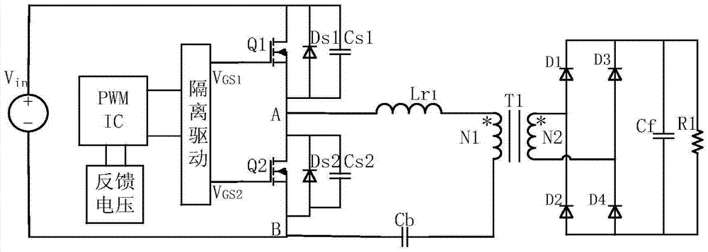
[0013] see figure 1 The schematic diagram of the topology of the asymmetrical half-bridge converter includes: PWM IC control chip, isolation drive circuit, half-bridge arm, isolation capacitor Cb and resonant inductor Lr1, power transformer T1, rectifier and filter circuit.

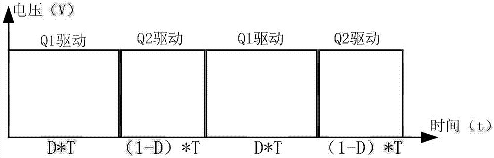
[0014] The PWM IC control chip, model UCC2897 of TI Company, outputs two pulses with complementary phases. The isolated driving circuit enhances the driving ability of the two pulses generated by the UCC2897 chip, and generates a pulse signal VGS1 that can be driven by floating ground, and the other pulse signal VGS2 that is complementary to VGS1. Both signals have dead time.

[0015] Semiconductor power devices Q1 and Q2 form a half-bridge bridge arm, DS1 is the internal parasitic diode of Q1, CS1 is the internal parasitic capacitance of Q1, DS2 is the internal parasitic diode of Q2, and CS2 is the internal parasitic capacitance of Q2. VGS1 drives Q1, VGS2 drives Q2, working in complementary mode (such...


PUM


Abstract

The invention relates to a topological structure of an asymmetrical half-bridge converter. A PWM control chip generates two phase-complementary driving pulses, and generates two driving signals VGS1 and VGS2 through an isolated driving circuit. With dead time, VGS1 drives power transistor Q1, and VGS2 drives power transistor Q2; power transistors Q1 and Q2 are connected in series to form a half-bridge bridge arm, and the midpoint A of the bridge arm is connected to The primary side coil of the power transformer T1; the secondary side coil of the power transformer T1 is connected with a full-wave rectification filter circuit, followed by a filter capacitor Cf to output a stable DC voltage Vo. The asymmetrical half-bridge converter of the present invention can conveniently realize DC voltage conversion through the resonant inductance, the parasitic capacitance of the power device, and the leakage inductance of the power transformer, and realize the high-voltage and low-current output of the power device. Zero-voltage conduction improves power conversion efficiency, is convenient to control, and has remarkable effects.

Description

technical field [0001] This patent belongs to the field of power electronic conversion, relates to the design and application of switching power supply, and aims to provide a switching power supply topology suitable for high voltage and small current output occasions. Background technique [0002] The so-called switching power supply is a power conversion architecture that converts DC voltage into different DC voltages. The power devices in the architecture work in the switching state by means of width-adjusting PWM. However, in the process of realizing high power density and high efficiency of the power supply, it is necessary to increase the switching frequency of the power device. If you continue to use the conventional switching method, you will encounter the problem of increased power loss during switching conversion. Therefore, on the basis of hard switching, the parasitic capacitance of the power device, the parasitic diode and the parasitic leakage inductance of th...

Claims


Application Information

Patent Timeline
Patent Type & Authority Applications(China)
IPC IPC(8): H02M3/335
CPCH02M3/33553
Inventor 张可银谢刘宏周雪莲
Owner LEIHUA ELECTRONICS TECH RES INST AVIATION IND OF CHINA
Why Eureka
Try Eureka