Determination method of CO2 displacement minimum miscible pressure of low and ultra-low permeability reservoir

A miscible pressure and measurement method technology, applied in earthwork drilling, wellbore/well components, sustainable manufacturing/processing, etc., can solve the problem of inability to truly reflect miscibility, inability to simulate oil layer conditions, low permeability reservoir permeability Poor performance and other problems, to achieve the effect of true and reliable measurement results

Active Publication Date: 2017-06-23
CHINA UNIV OF PETROLEUM (BEIJING)
View PDF11 Cites 30 Cited by
  • Summary
  • Abstract
  • Description
  • Claims
  • Application Information

AI Technical Summary

Problems solved by technology

[0004] 1. There are different degrees of cementation in actual reservoirs, and the particle size is not evenly distributed, so the narrow tube model cannot simulate the real oil layer conditions. In fact, the pore throat size of the thin tube model is usually the same as that of the real reservoir. There is an order of magnitude gap, which leads to the fact that the minimum miscible pressure determined by the thin tube model cannot truly reflect the CO2 under reservoir conditions. 2 Miscibility with crude oil;
[0005] 2. (Extra) low permeability reservoirs have poor permeability, and the reservoir permeability is usually less than 100×10 -3 μm 2 , and the quartz sand or glass beads required to fill the thin tube model are usually large in particle size, and the permeability of the filled thin tube model is usually above thousands of millidarcy, which cannot simulate low-permeability reservoirs at all;
[0006] 3. Serious viscous fingering and reservoir heterogeneity often exist in actual reservoirs, especially (extra) low-permeability reservoirs. However, in the thin tube model, uniform quartz sand or glass beads are filled, which excludes Due to the influence of factors such as mobility ratio, viscous fingering, gravity separation, and reservoir heterogeneity, the minimum miscible pressure determined by the thin tube model cannot truly reflect the miscible pressure under reservoir conditions;
[0007] 4. From the perspective of experimental operation, multiple sets of repeated displacement experiments are required to determine the minimum miscible pressure. In the process of narrow tube experiment operation, the thin tube model is often reused, so at the beginning of each displacement experiment Sometimes it needs to be cleaned with reagents such as toluene and petroleum ether. Not only is the operation cumbersome, but if the above reagents are not completely removed, their residues will affect subsequent experiments, resulting in the inability to accurately measure the minimum miscible pressure.

Method used


Image

  • Determination method of CO2 displacement minimum miscible pressure of low and ultra-low permeability reservoir
  • Determination method of CO2 displacement minimum miscible pressure of low and ultra-low permeability reservoir
  • Determination method of CO2 displacement minimum miscible pressure of low and ultra-low permeability reservoir

Examples


Embodiment 1

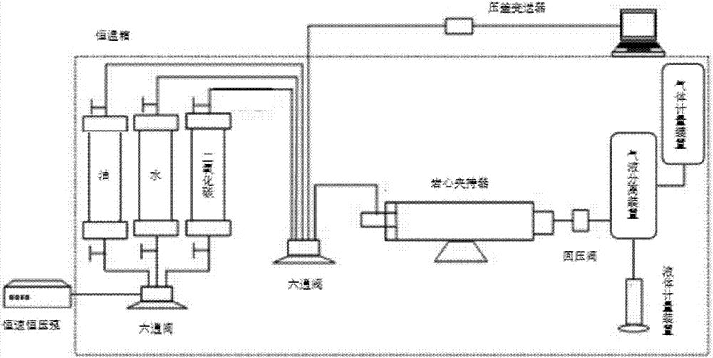
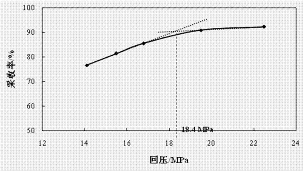
[0058] Adopt a kind of low, ultra-low permeability reservoir CO of the present invention 2 The method for measuring the minimum miscible pressure of flooding, measuring the CO2 in a certain target oilfield block reservoir 2 The flooding minimum miscible pressure includes the following steps:

[0059] 1) A series of artificially pressed ultra-low permeability cores were used as the indoor measurement of CO in (extra) low permeability reservoirs. 2 The physical model core of the minimum miscible pressure is flooded, and the gas permeability of the physical model core is 5×10 -3 μm 2 , the core size is 30×4.5×4.5cm3 , and dry the physical model core, measure the length, width and height of the physical model core, and calculate the apparent volume of the physical model core;

[0060] 2) Carry out anti-corrosion treatment on the physical model core: evenly apply epoxy resin coating on the surface of the physical model core to prevent CO 2 Corrosion of the rubber tube of the co...

Embodiment 2

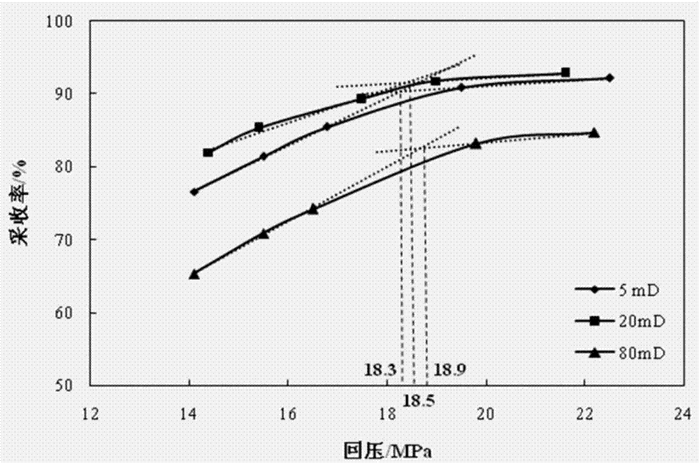
[0082] In this example, the ultra-low permeability cores (gas permeability 5×10 -3 μm 2 ), low-permeability cores (gas permeability 20×10 -3 μm 2 ), medium and low permeability cores (gas permeability 80×10 -3 μm 2 ) as a physical model core, adopt a kind of low, ultra-low permeability reservoir CO of the present invention 2 Determination method of minimum miscibility pressure for flooding CO2 under different permeability conditions 2 and the minimum miscible pressure of formation crude oil, the specific steps are basically the same as in Example 1, and the experimental results of the minimum miscible pressure test of rock cores with different permeability are shown in Table 4; 2 The relationship curve between flooding recovery and back pressure, such as image 3 shown.

[0083] Table 4 CO of different permeability cores 2 Experimental results of flooding minimum miscible pressure test

[0084]

[0085] From Table 4 and image 3 The following conclusions can be dr...

Embodiment 3

[0089] In this example, homogeneous rock cores (gas permeability 5×10 -3 μm 2 ), heterogeneous cores with a permeability difference of 10 (the permeability of the low permeability layer is 5×10 -3 μm 2 , High permeability layer permeability 50×10 -3 μm 2 ), heterogeneous cores with a permeability difference of 30 (the permeability of the low-permeability layer is 5×10 -3 μm 2 , high permeability layer permeability 150×10 -3 μm 2 ) as a physical model core, adopt a kind of low, ultra-low permeability reservoir CO of the present invention 2 Determination method of minimum miscibility pressure for flooding Test different degrees of heterogeneous core CO2 The minimum miscible pressure with formation crude oil, the specific steps are basically the same as in Example 1, and different degrees of heterogeneous core CO 2 Table 5 shows the experimental results of flooding minimum miscible pressure; 2 The relationship curve between flooding recovery and back pressure, such as ...


PUM


Abstract

The invention relates to a determination method of the CO2 displacement minimum miscible pressure of a low and ultra-low permeability reservoir. The method includes the steps of 1, selecting a physical model core; 2, conducting anti-corrosion treatment on the physical model core; 3, applying confining pressure to the physical model core and conducting vacuumizing; 4, measuring the pore volume of the physical model core and calculating the porosity of the physical model core; 5, heating the physical model core to a target formation temperature and measuring the permeability to water; 6, simulating the oil saturation process, recording the volume of saturated simulated oil and calculating the initial oil saturation; 7, simulating CO2 displacement, recording the displacement pressure and the outlet end liquid and gas volumes and calculating the CO2 displacement recovery rate; 8, replacing the physical model core with another physical model core with the same permeability and repeating the steps 1-7 to obtain CO2 displacement recovery rates under different displacement pressures and return pressures; 9, drawing a relation curve of the CO2 displacement recovery rates and the return pressures, wherein the return pressure corresponding to the recovery rate inflection point on the relation curve is the CO2 displacement minimum miscible pressure of the low and ultra-low permeability reservoir.

Description

technical field [0001] The invention belongs to low permeability reservoir CO 2 In the field of flooding development technology, especially a kind of low and ultra-low permeability reservoir CO 2 The determination method of minimum miscibility pressure. Background technique [0002] Many scholars at home and abroad have shown that among many methods of enhancing oil recovery, CO 2 Miscible flooding plays an important role. In the United States, Canada and other regions, CO 2 Miscible flooding has achieved great success in enhancing oil recovery. And with my country's CO 2 The continuous discovery of gas sources and the CO 2 The maturity of the capture technology, in my country's CO 2 Miscible flooding technology will also become a cost-effective enhanced oil recovery technology. CO 2 The miscibility of is a dynamic multi-stage contact miscible process, that is, relying on the injected CO in the flow process 2 Mass transfer of the components caused by repeated contac...

Claims


Application Information

Patent Timeline
Patent Type & Authority Applications(China)
IPC IPC(8): E21B43/16
CPCE21B43/164Y02P90/70
Inventor 赵凤兰郝宏达侯吉瑞付忠凤李文峰侯利斌王志兴
Owner CHINA UNIV OF PETROLEUM (BEIJING)
Why Eureka
Try Eureka