
Concentric casing heat exchange tube

A technology of concentric sleeves and heat exchange tubes, applied in geothermal energy, heating fuel, household heating, etc., can solve the problems of increased construction cost, increased construction difficulty and cost, and affected heat exchange efficiency, etc., to achieve the cost of backfill materials The effect of reducing and reducing the number of heat exchange tubes and improving heat exchange efficiency

Pending Publication Date: 2017-06-23
JIANGSU GEOLOGY & GEOTHERMAL ENERGY
View PDF7 Cites 6 Cited by
  • Summary
  • Abstract
  • Description
  • Claims
  • Application Information

AI Technical Summary

Problems solved by technology

In addition, according to the "Technical Specifications for Ground Source Heat Pump System Engineering" (GB 50366-2009), during the construction of conventional double U25 and single U32 buried pipes, it is required to set up a support pipe clamp every 5 meters to prevent PE pipes from If they are bonded together, they will cause a "thermal short circuit", form ineffective heat transfer, and reduce the heat transfer efficiency of the buried pipe; however, in actual construction, the pipe clip cannot be installed basically, and the main reasons for the existence are as follows: 1) The buried pipe During construction, before inserting the buried pipe into the borehole, it is necessary to spread the 100-meter-long buried pipe horizontally on the edge of the hole, and then install pipe clamps. Taking double U25-type buried pipes as an example, four 100-meter-long buried pipes , after the De25 PE pipe is installed with pipe clips, it is difficult to lower the horizontal pipe into the vertical borehole, the construction is difficult, and there are site requirements for the installation of pipe clips; It is close to the wall of the borehole, and the hole collapses due to friction, impact, etc. during the process of lowering the pipe, which increases the difficulty and cost of construction; Fill in special materials (the main components are concrete, sand and bentonite, the proportion of which is determined according to different surrounding geological conditions) to ensure the quality of the holes, but a pipe clamp every 5 meters will prevent the backfill material from being backfilled in the middle of the pipe. It is easy to cause the upper part of the backfill material to bridge the lower part of the cavity, which affects the heat transfer efficiency
The existence of tube clamps is to enhance the heat exchange capacity, but at the same time it brings increased construction costs and risks. Therefore, it is difficult to realize the installation of tube clamps during construction
[0004] Drilling holes with a diameter of not less than 150mm are difficult to construct in bedrock areas, and the construction cost increases significantly, which is reflected in the following aspects: 1) The larger the hole diameter, the slower the drilling rate, and the cost of personnel, oil and machinery The greater the loss of equipment; 2) The larger the hole diameter, the more backfill materials are required, and the greater the cost of personnel and materials; 3) The construction period increases significantly, and various costs increase significantly
[0005] For multiple pipes in one borehole, the adjacent pipes form an invalid heat exchange area due to the lack of heat transfer temperature difference, which also causes waste of materials
[0006] Due to the above reasons, the conventional double U25 type and single U32 type buried pipes increase the cost of the outdoor buried pipe heat exchange system due to objective technical reasons and requirements, which limits the effective promotion of ground source heat pump technology

Method used


Image

  • Concentric casing heat exchange tube
  • Concentric casing heat exchange tube
  • Concentric casing heat exchange tube

Examples


Embodiment Construction

[0029] The present invention will be further explained below in conjunction with the accompanying drawings and specific embodiments. It should be understood that the following specific embodiments are only used to illustrate the present invention and are not intended to limit the scope of the present invention. It should be noted that the words "front", "rear", "left", "right", "upper" and "lower" used in the following description refer to the directions in the drawings, and the words "inner" and "outer ” refer to directions towards or away from the geometric center of a particular part, respectively.

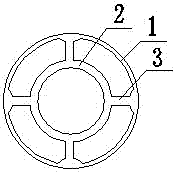
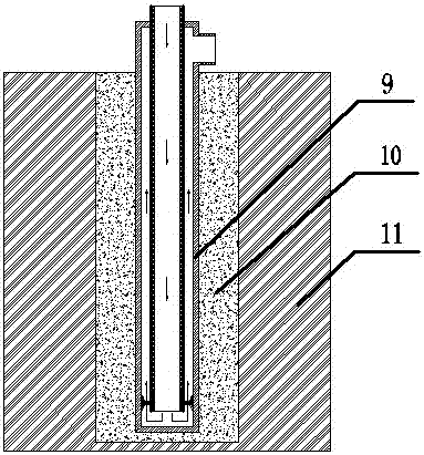
[0030] As shown in the figure, a concentric casing heat exchange tube according to the present invention is made of HDPE (high density polyethylene) 100 type, with a pressure bearing capacity of 1.6MPa and a long service life; the inner side of the inner tube 2 is a water inlet tube , when the water flows to the bottom of the concentric sleeve type heat exchange tube, it return...


PUM


Abstract

The invention discloses a concentric casing heat exchange tube which comprises a tube body, an inner tube and tube head brackets, wherein a limiting hole is formed in the upper part of the tube body; a water outlet is formed in the upper part of a side of the tube body; the inner tube is inserted into the limiting hole; a gap is formed between the lower part of the inner tube and the lower part of the tube body; the tube head brackets are symmetrically arranged below sides of the inner tube; a thermal-insulating coating is arranged on the outer side of the inner tube; an interlayer is arranged between the outer side of the inner tube and the inner side of the tube body; the tube body is coaxial with the inner tube. The concentric casing heat exchange tube is low in drilling workload, small in heat exchange tube number, low in cost and high in heat exchange efficiency, has remarkable economical efficiency and practicability, and has very wide application prospects.

Description

technical field [0001] The invention belongs to the field of geothermal heat exchange tubes, in particular to a concentric casing heat exchange tube. Background technique [0002] As an effective form of shallow geothermal energy utilization, ground source heat pump technology has received great attention and promotion at home and abroad for its greenness, environmental protection, renewability and high utilization rate. It is accompanied by ground source heat pump outdoor buried pipes. The high cost of the heat exchange system greatly limits its popularization and application. There are two types of conventional outdoor buried pipe heat exchange systems: double U25 shape and single U32 shape. [0003] According to the requirements of the drilling process, the required diameter of the geological drilling hole for conventional buried pipes is not less than 150mm. In addition, according to the "Technical Specifications for Ground Source Heat Pump System Engineering" (GB 5036...

Claims


Application Information

Patent Timeline
Patent Type & Authority Applications(China)
IPC IPC(8): F24J3/08
CPCF24T10/17F24T2010/50Y02E10/10
Inventor 李贵
Owner JIANGSU GEOLOGY & GEOTHERMAL ENERGY
Learn More