
Multi-inverter parallel current-sharing control method

A multi-inverter and current control technology, applied in the direction of converting AC power input to DC power output, output power conversion devices, electrical components, etc., to achieve the effects of suppressing circulation problems, solving circulation problems, and solving uneven current problems

Inactive Publication Date: 2017-06-23
范洪国
View PDF0 Cites 6 Cited by
  • Summary
  • Abstract
  • Description
  • Claims
  • Application Information

AI Technical Summary

Problems solved by technology

[0005] In order to overcome the problems of circulating current suppression and current sharing control, the present invention proposes a current sharing control method with multiple inverters connected in parallel

Method used


Image

  • Multi-inverter parallel current-sharing control method
  • Multi-inverter parallel current-sharing control method
  • Multi-inverter parallel current-sharing control method

Examples


Embodiment Construction

[0017] specific implementation plan

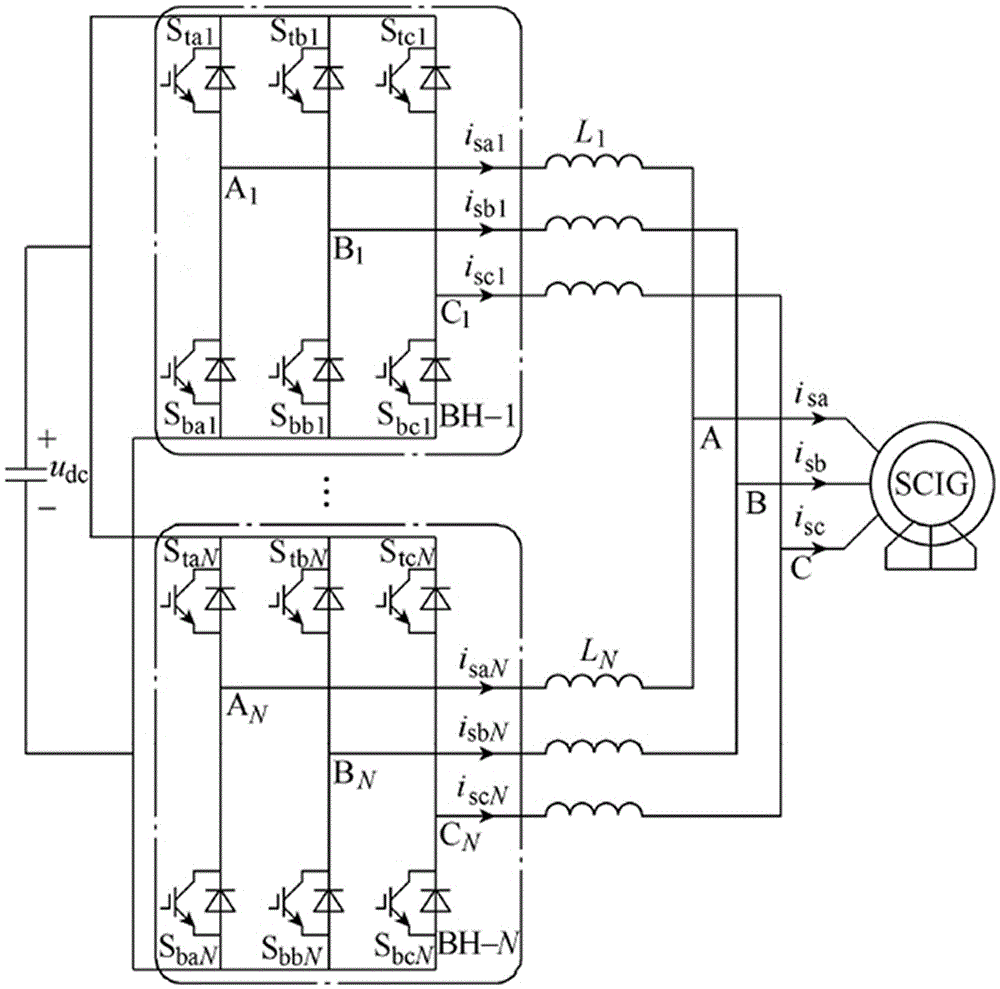
[0018] The system consists of N three-phase IGBT fully-controlled bridges (BH-1,..., BH-N) with the same structure. The DC terminals of all N three-phase fully-controlled bridges are connected together. The three-phase fully-controlled bridges The output ends are connected to the three-phase input stator end of the asynchronous motor through current sharing reactors L1,..., LN. The control objectives of multi-parallel inverters are to control the total output current balance of the inverters, to suppress the circulating current among the sub-inverters, and to suppress the non-uniformity of the output current of each sub-inverter.

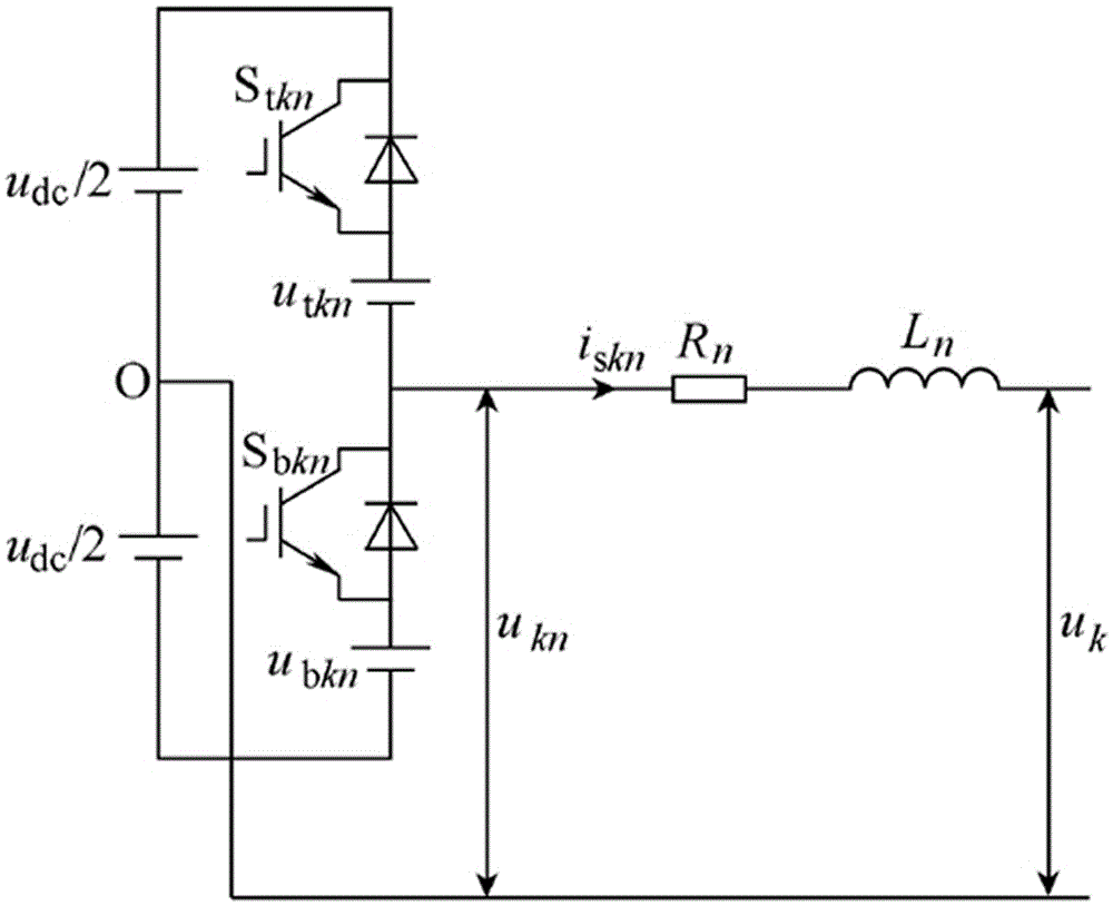
[0019] figure 2 , is the equivalent schematic diagram of the output of the k-phase bridge arm of the nth parallel inverter, in the figure is the turn-on voltage drop of the upper switch IGBT; For the turn-on voltage drop of the down-side IGBT, set the virtual midpoint of the bus capacitor as the reference ...


PUM


Abstract

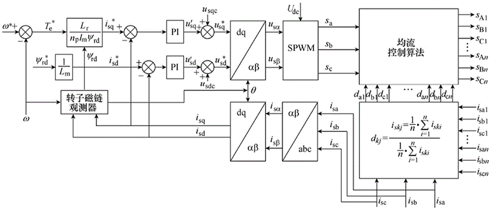
The invention discloses a multi-inverter parallel current equalization control method, which comprises four parts: multi-inverter parallel circuit, delay pulse width compensation, SPWM modulation and current equalization control. The circulating current problem existing in the parallel system is solved, and the uneven current problem of the output current of the inverter is solved by pulse delay compensation. The advantage of the pulse modulation method being the closed-loop compensation method is that it can realize automatic compensation and can adapt to the multi-inverter parallel system with different parallel numbers. Therefore, by changing the pulse modulation method to SPWM modulation method, the circulating current in the parallel system is effectively suppressed. question.

Description

technical field [0001] The invention relates to a power inverter device, in particular to a current equalization control method using Chinese multi-inverters connected in parallel. Background technique [0002] In recent years, with the rapid development of power electronics technology, inverters are increasingly developing towards large capacity. Especially in the field of new energy applications, such as wind power generation, photovoltaic power generation and energy storage power stations, etc., the capacity of the inverter can be as high as several MW. However, limited by the current capacity of power switching devices, in high-power applications, especially in the field of low-voltage and high-current, it is difficult for a single inverter technical solution to meet the power output requirements, so the technical solution of multiple inverters connected in parallel can only be used to improve output power of the inverter. [0003] The use of parallel technology makes ...

Claims


Application Information

Patent Timeline
Patent Type & Authority Applications(China)
IPC IPC(8): H02M7/5387H02M7/5395
CPCH02M7/53873H02M7/5395
Inventor 范洪国
Owner 范洪国
Learn More