Fan foundation ring with wing plates and design method and application of fan foundation ring

A wind turbine foundation and foundation ring technology, applied in foundation structure engineering, sheet pile walls, wind power generation, etc., can solve problems such as small constraint stiffness, unreasonable foundation ring shape, lack of calculation methods for foundation ring reinforcement schemes, etc., to achieve improved resistance The effect of bending stiffness

Inactive Publication Date: 2017-06-27
ZHEJIANG UNIV
View PDF6 Cites 6 Cited by
  • Summary
  • Abstract
  • Description
  • Claims
  • Application Information

AI Technical Summary

Problems solved by technology

In actual engineering, many detachment cracks between the foundation ring and the surrounding concrete occur on the top surface of the foundation. Therefore, the effect of placing the wing plate on the lower part of the foundation ring still needs to be further optimized. The existing patents and literatures do not give the lower part. Calculation method for base rings of flanges and enlarged base plates
In addition, the base ring of the lower wing plate can only be used for new construction, when the conventional base ring ( figure 1 , no stiffening plate) after the damage occurs, since the surrounding of the foundation ring has been poured with concrete and dense steel bars are arranged, it is impossible to install the wing plate and the enlarged bottom plate at the lower part of the conventional foundation ring, that is: the lower installation of the wing plate and the enlarged bottom plate The base ring cannot be applied to the reinforcement of the existing wind turbine base ring
[0005] In view of the damage of the foundation ring of the wind turbine, some literatures mention the reinforcement m...

Method used


Image

  • Fan foundation ring with wing plates and design method and application of fan foundation ring
  • Fan foundation ring with wing plates and design method and application of fan foundation ring
  • Fan foundation ring with wing plates and design method and application of fan foundation ring

Examples


Embodiment

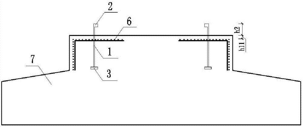
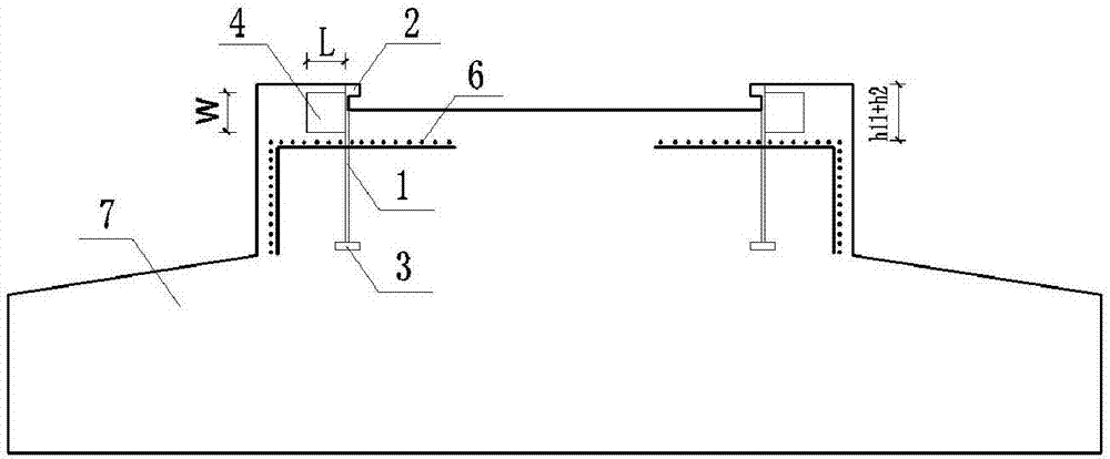
[0066] The concrete around the foundation ring of a wind power foundation is broken, and the crack between the foundation ring and the concrete is too large. Taking this project as an example, the effect of adopting the method of adding wings to strengthen the fan foundation is illustrated. The foundation ring of the cylindrical fan is buried in the concrete foundation, the original foundation and the foundation ring, such as Figure 9 As shown, the diameter of the foundation ring is 4.2m, the burial depth of the foundation ring in the concrete is h1=1.25m, the thickness of the concrete protective layer of the reinforcement on the top surface of the foundation is h11=0.15m, and the height of the foundation ring exposed to the top surface of the concrete is h2 =0.4m, the bottom of the foundation ring is about 2.2m away from the bottom of the entire concrete foundation.

[0067] Establish a three-dimensional finite element model of the fan foundation, and calculate the stress a...


PUM


Abstract

The invention discloses a fan foundation ring with wing plates and a design method and application of the fan foundation ring. The fan foundation ring comprises fan foundation ring bodies being cylindrical steel members. The upper top surfaces of the cylindrical steel members are provided with foundation ring upper flanges, the lower bottom surfaces of the cylindrical steel members are provided with foundation ring lower flanges, and a plurality of the vertical wing plates or the horizontal wing plates are laid on the upper cylinder walls of the fan foundation ring bodies in the circumferential direction. The invention further provides a design method and application of the fan foundation ring with the added wing plates. The invention provides a high-precision numerical simulation method which can effectively evaluate the improvement condition of bearing capacity of fan foundation by the added wing plates and further provides an effective and feasible method for reinforcing the fan foundation, significant alteration and breakage to the original concrete and reinforcing bars do not occur, construction is convenient under the condition of not affecting operation of an upper fan, the construction period is short, and the reinforcement cost is reduced.

Description

technical field [0001] The invention belongs to the fields of wind power generation and new energy, and in particular relates to a fan foundation ring with partial wing plates and a method for reinforcing the fan foundation by using the wing plates. Background technique [0002] Wind power has developed rapidly. In recent years, a large number of large-scale wind farms have been built in my country. A wind turbine is mainly composed of a nacelle, blades, tower, foundation ring, foundation, etc. The nacelle and blades are located on the top of the tower, and the tower and the foundation are connected by a foundation ring. The base ring is a large diameter steel cylinder member with flanges on the top and bottom of the cylinder ( figure 1 ). The method of connecting the foundation ring is: most of the lower part of the foundation ring is buried in the foundation concrete, a small section of the upper part of the foundation ring is exposed to the foundation concrete, and the ...

Claims


Application Information

Patent Timeline
IPC IPC(8): E04H12/22E02D5/80E02D27/42F03D13/20
CPCY02E10/728E04H12/2292E02D5/80E02D27/425
Inventor 王振宇
Owner ZHEJIANG UNIV
Why Eureka
Try Eureka