Supercharge Your Innovation With Domain-Expert AI Agents!

Engine exhausted gas post-treatment device

An exhaust post-treatment and engine technology, applied in exhaust treatment, exhaust devices, engine components, etc., to achieve standardized design, reduce the risk of crystallization, and improve efficiency

Active Publication Date: 2017-06-27
TENNECO SUZHOU EMISSION SYST
View PDF6 Cites 0 Cited by
  • Summary
  • Abstract
  • Description
  • Claims
  • Application Information

AI Technical Summary

Problems solved by technology

[0005] However, because the cost and performance of the mixing tube sometimes have advantages over the static mixer, the overall size of the engine exhaust aftertreatment device is limited by the customer's installation size and cannot be infinitely wide, and the mixing structure on the mixing tube It also has a certain length, so how to solve the problem of installing this type of mixing tube even when the overall size of the engine exhaust aftertreatment device is relatively small has become one of the technical problems that need to be solved in the industry.

Method used


Image

  • Engine exhausted gas post-treatment device
  • Engine exhausted gas post-treatment device
  • Engine exhausted gas post-treatment device

Examples


Embodiment Construction

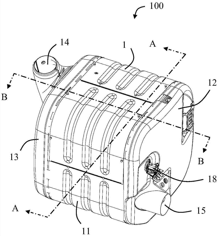
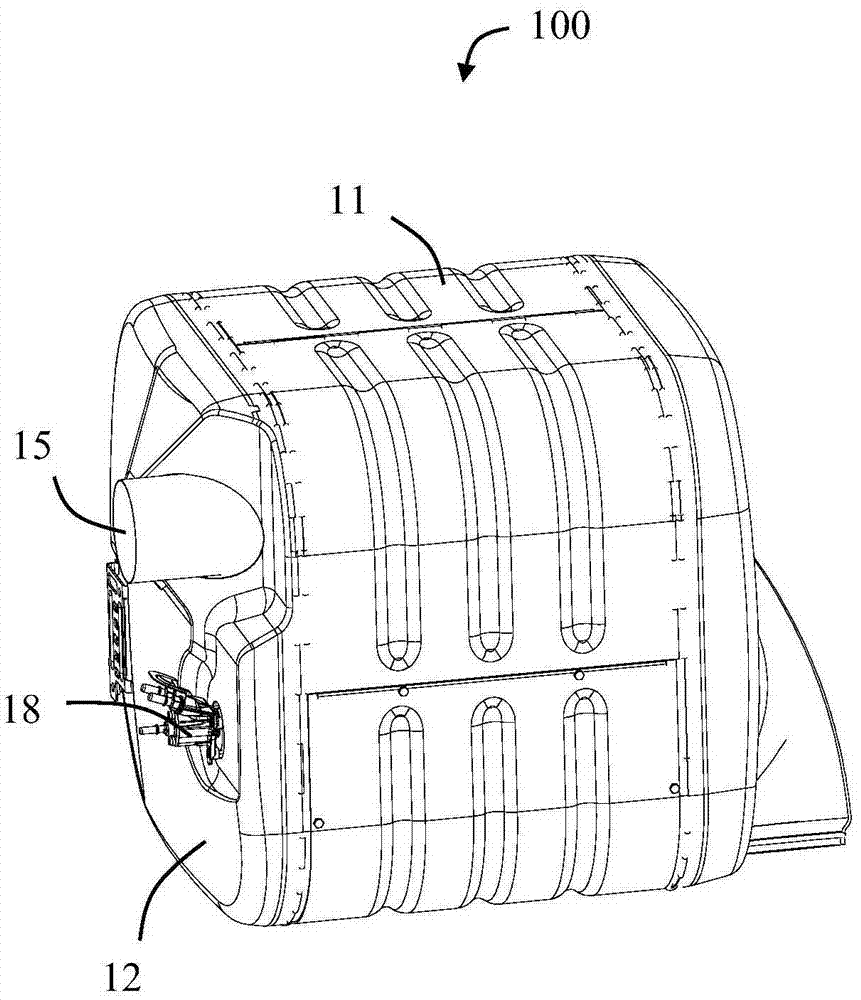
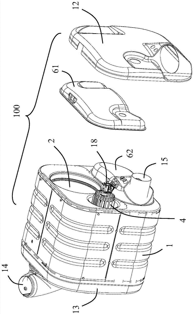
[0028] Please refer to figure 1 and figure 2 As shown, the present invention discloses an engine exhaust aftertreatment device 100, which includes an upstream aftertreatment assembly 2 with a casing 1 located in the casing 1, and a downstream aftertreatment assembly connected in series with the upstream aftertreatment assembly 2 3. And a mixing pipe 4 for connecting the upstream and downstream aftertreatment components 2 and 3 in series.

[0029] In the illustrated embodiment of the present invention, the upstream aftertreatment component 2 includes an oxidation catalytic converter (DOC) 21 and / or a particulate filter (DPF) 22, wherein the oxidation catalytic converter 21 is located at upstream of the particulate trap 22 to provide a suitable temperature when the particulate trap 22 is regenerated.

[0030] The downstream aftertreatment component 3 includes a selective catalytic reductant (SCR). In the illustrated embodiment of the present invention, the selective catalyti...


PUM


Abstract

An engine exhausted gas post-treatment device comprises an inlet, a first cavity, a mixing pipe, a downstream post-treatment assembly and an outlet. The mixing pipe comprises a hollow inner cavity, a plurality of fins and a plurality of slots corresponding to the fins. The engine exhausted gas post-treatment device comprises a shell. The shell comprises a first end plate and a first inner side plate. The first inner side plate is fixed to the first end plate so that the first cavity can be formed between the first end plate and the first inner side plate. The shell comprises an expansion cavity communicating with the first cavity. The expansion cavity and the first cavity are located in the two sides of the first end plate correspondingly. The fins and the slots are both contained in the first cavity and the expansion cavity. Through the arrangement, volute exhausted gas can improve the mixing uniformity with an atomized urea solution; and in addition, through the arrangement of the expansion cavity, installation of the mixing pipe is not limited by the overall size of the engine exhaust post-treatment device.

Description

technical field [0001] The invention relates to an engine exhaust aftertreatment device. Background technique [0002] Engine exhaust after-treatment devices (such as diesel engine exhaust after-treatment devices) are mainly used to treat or purify toxic and harmful substances in exhaust. Toxic substances in exhaust mainly include hydrocarbons, carbon monoxide, nitrogen oxides and particulate matter. [0003] In the prior art, there has been a combination of an oxidation catalytic converter (DOC), a particulate filter (DPF) and a selective catalytic reductant (SCR) system to improve the efficiency of exhaust gas treatment. In one scheme, the oxidation-type catalytic converter and the particulate filter are arranged in series in the first casing; the selective catalytic reducing agent is arranged in the second casing; 1. The second shells are connected in series. [0004] In order to allow the exhaust gas to be uniformly mixed with the atomized urea solution in the connect...

Claims


Application Information

Patent Timeline
Patent Type & Authority Applications(China)
IPC IPC(8): F01N3/28F01N3/20
CPCF01N3/206F01N3/28F01N2330/38F01N2610/02
Inventor 王伟童毅君王聪毛伟赵治国
Owner TENNECO SUZHOU EMISSION SYST
Features
  • R&D
  • Intellectual Property
  • Life Sciences
  • Materials
  • Tech Scout
  • Unparalleled Data Quality
  • Higher Quality Content
  • 60% Fewer Hallucinations
Learn More