Generator of trigger signal in pxie bus
A technology for generating devices and triggering signals, applied in the field of PXIe systems, can solve the problems of occupying additional space in the PXIe system, high interconnection costs, and much space in the PXIe system, reducing the occupied space and the number of chip pins, and reducing interconnection costs. Effect
- Summary
- Abstract
- Description
- Claims
- Application Information
AI Technical Summary
Problems solved by technology
Method used
Image
Examples
no. 1 example
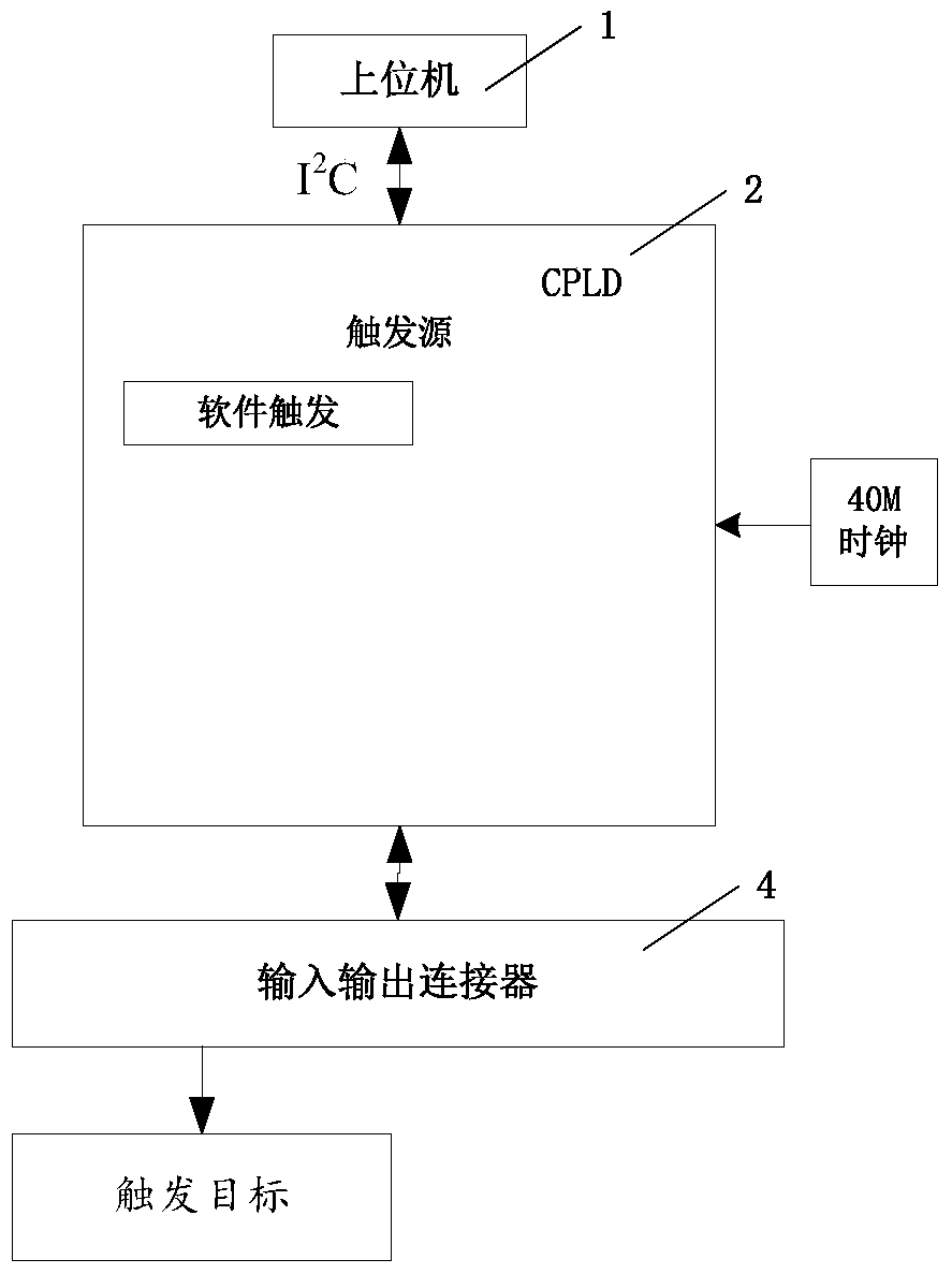
[0018] like figure 1 Shown, the generating device of trigger signal in the PXIe bus of the present embodiment comprises host computer 1 as computer control module, CPLD chip 2 and input-output connector 4, and host computer 1 passes through I 2 The C bus is connected to the CPLD chip 2, and the CPLD chip 2 is connected to the input and output connector 4, wherein the CPLD chip 2 realizes the software trigger, and the host computer 1 routes the software trigger realized by the CPLD chip 2 to the trigger target through the input and output connector 4.
[0019] As preferably, CPLD chip 2 passes through I 2 The C bus acquires the configuration information corresponding to the software trigger on the host computer 1, so as to adjust the pulse width and polarity of the software trigger signal according to the configuration information.
[0020] Further, as figure 1 As shown, the trigger signal generating device of this embodiment also includes a crystal oscillator source connecte...
no. 2 example
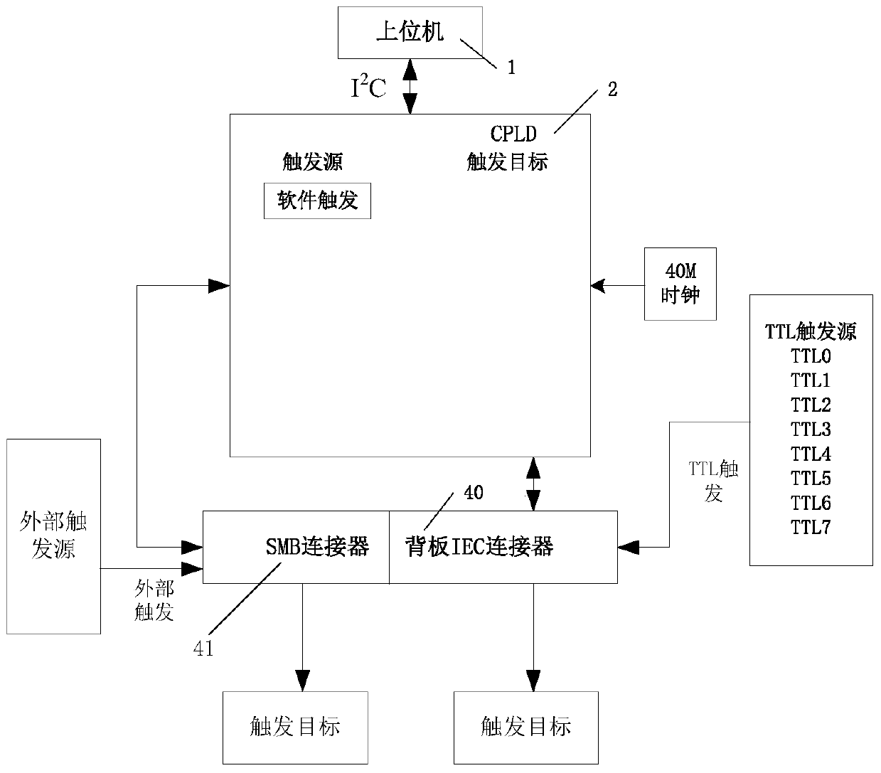
[0023] like figure 2 As shown, the present embodiment is on the basis of the first embodiment, in the generation device of the trigger signal in the PXIe bus of the present embodiment, the input and output connector 4 comprises the SMB connector 41 (arranged on the front panel of the PXIe controller) And IEC connector 40 (set in PXIe controller), SMB connector 41 realizes the input and output of external trigger, IEC connector 40 realizes the input and output of TTL trigger, and the register configuration of host computer 1 control CPLD chip 2 can be accurate Realize the following trigger routing methods: external trigger trigger to TTL trigger, TTL trigger trigger to external trigger, software trigger trigger to external trigger, and software trigger trigger to TTL trigger. There are 8 TTL trigger signal lines on the backplane of the PXIe bus, and 1 external trigger signal line, thus triggering to the external trigger connector of the PXIe bus ( SMB connector 41), that is, ...
no. 3 example
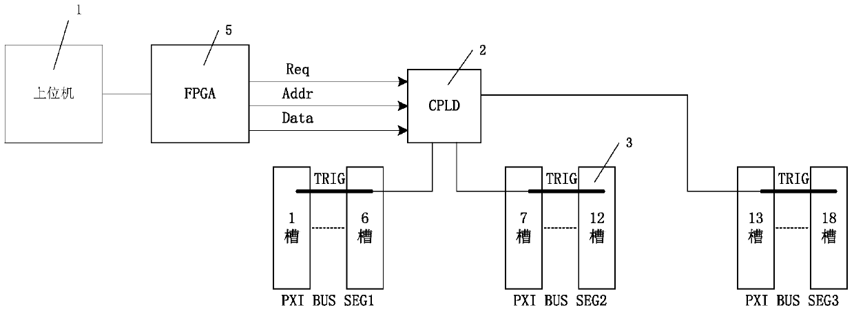
[0027] like image 3 As shown, the host computer 1 controls the CPLD through the FPGA chip 5, the CPLD chip 2 is connected to the PXIe bus segment of the backplane of the PXIe system through the IEC connector 4, and the FPGA chip 5 sets the trigger route through the CPLD chip 2. This embodiment is applied in the PXIe backplane design. Part 3 is 18 slots on the backplane, which are divided into three PXI bus segments: slots 1 to 6 are PXI bussegment1, slots 7 to 12 are PXI bus segment2, and slots 13 to 12 are PXI bus segment2. Slot 18 is PXI bus segment3, these slots can be inserted into TTL trigger source, among them, CPLD chip 2 is EPM240F100 to realize trigger routing, and FPGA chip 5 and CPLD chip 2 pass serial bus I 2 C communicates, sends the control command to the CPLD chip 2, and sets the trigger routing information. By default, different PXI bus segments are physically isolated. If triggering between different PXI bus segments is required, it is necessary to configure...
PUM
 Abstract
Description
Claims
Application Information
 - R&D Engineer
- R&D Manager
- IP Professional
- Industry Leading Data Capabilities
- Powerful AI technology
- Patent DNA Extraction
Browse by: Latest US Patents, China's latest patents, Technical Efficacy Thesaurus, Application Domain, Technology Topic, Popular Technical Reports.
© 2024 PatSnap. All rights reserved.Legal|Privacy policy|Modern Slavery Act Transparency Statement|Sitemap|About US| Contact US: help@patsnap.com


