Multibeam cavity-backed high gain antenna array applicable to millimeter wave communication

A high-gain antenna, multi-beam technology, applied in antenna arrays, antennas, antenna coupling and other directions, can solve the problem of low gain of multi-beam patch antenna arrays, and achieve high gain and improve antenna gain.

Inactive Publication Date: 2017-06-27
X TRIP INFORMATION TECH CO LTD
View PDF4 Cites 20 Cited by
  • Summary
  • Abstract
  • Description
  • Claims
  • Application Information

AI Technical Summary

Problems solved by technology

[0003] The main purpose of the present invention is to provide a multi-beam cavity-backed high-gain antenna array suitable for millimeter wave communication, aiming to solve the technical problem of low gain of the existing multi-beam patch antenna array

Method used


Image

  • Multibeam cavity-backed high gain antenna array applicable to millimeter wave communication
  • Multibeam cavity-backed high gain antenna array applicable to millimeter wave communication
  • Multibeam cavity-backed high gain antenna array applicable to millimeter wave communication

Examples


Embodiment Construction

[0021] In order to further illustrate the technical means and effects of the present invention to achieve the above objectives, the specific implementation, structure, features and effects of the present invention will be described in detail below in conjunction with the accompanying drawings and preferred embodiments. It should be understood that the specific embodiments described here are only used to explain the present invention, not to limit the present invention.

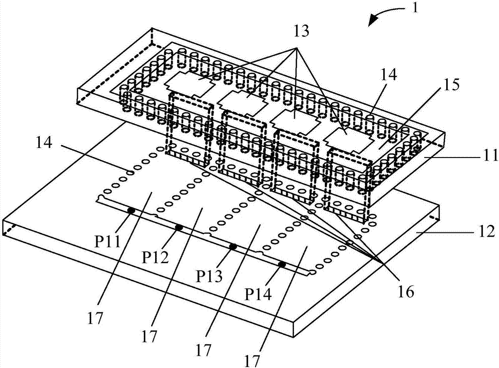
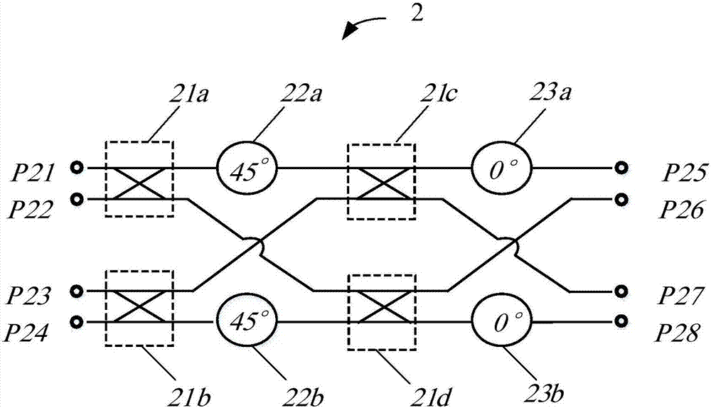
[0022] refer to figure 1 as shown, figure 1 It is a structural schematic diagram of a preferred embodiment of a multi-beam cavity-backed high-gain antenna array suitable for millimeter wave communication in the present invention; figure 2 It is a schematic circuit diagram of a preferred embodiment of a beamforming feeding network in a cavity-backed multi-beam high-gain antenna array suitable for millimeter wave communication according to the present invention. In this embodiment, the multi-beam cavity-backe...


PUM


Abstract

The invention discloses a multibeam cavity-backed high gain antenna array applicable to millimeter wave communication. The antenna array comprises a radiation patch antenna and a wave beam molding feed network, wherein the radiation patch antenna comprises an upper substrate and a lower substrate, an upper surface of the upper substrate is provided with four antenna units with intervals, multiple metallization through holes are circled at periphery of the four antenna units to form a metal cavity, the lower substrate is provided with four substrate integration waveguides, multiple metallization through holes are circled to form each substrate integration waveguide, the four substrate integration waveguides are provided with four input ends of the radiation patch antenna, and the four input ends of the radiation patch antenna are respectively correspondingly connected with four output ends of the wave beam molding feed network. When the four input ends of the wave beam molding feed network are inputted with four paths of electromagnetic wave beam excitation, and phase differences of the adjacent output ends are respectively 45 DEG, 135 DEG, -135 DEG and -45 DEG. The antenna array is advantaged in that surface electromagnetic waves can be effectively inhibited through the added cavity-backed structure, and antenna gain is further improved.

Description

technical field [0001] The invention relates to the technical field of microwave communication, in particular to a multi-beam cavity-backed high-gain antenna array suitable for millimeter wave communication. Background technique [0002] With the rise of 5G, the millimeter-wave frequency band, especially the 60GHz frequency band, has been widely studied by scholars due to the higher data transmission rate and large transmission capacity of the communication system. However, the 60GHz frequency band is at the absorption peak of the atmosphere, so the path loss is very large. To deal with this problem, high-gain antennas must be used to compensate for the path loss. However, for high-gain antennas, due to their high directivity, the coverage of their beams is limited. In order to obtain high gain and cover a wider range at the same time, multi-beam antennas are a good choice. However, the gain of the traditional 1×4 multi-beam patch antenna array is low. The reason is that o...

Claims


Application Information

Patent Timeline
Patent Type & Authority Applications(China)
IPC IPC(8): H01Q21/00H01Q1/38H01Q1/50H01Q1/52
CPCH01Q1/38H01Q1/50H01Q1/526H01Q21/0006
Inventor 朱剑锋邓力李书芳张贯京葛新科高伟明张红治
Owner X TRIP INFORMATION TECH CO LTD
Why Eureka
Try Eureka