Optical power control method and device for optical fiber vibration sensing

A technology of optical power control and optical fiber vibration, applied in measurement devices, using wave/particle radiation, instruments, etc., can solve the problem of inability to obtain relatively stable received optical power at the optical detector end, and prevent the light source from working in an unstable state. The effect of reducing negative effects

Active Publication Date: 2019-12-10
宏安集团有限公司 +1
View PDF7 Cites 0 Cited by
  • Summary
  • Abstract
  • Description
  • Claims
  • Application Information

AI Technical Summary

Problems solved by technology

[0005] Aiming at the above defects or improvement needs of the prior art, the present invention provides an optical power control method and device for optical fiber vibration sensing, the purpose of which is to provide a low-cost vibration sensing system that can receive optical signals A method for obtaining relatively stable received optical power at the end, thereby solving the technical problem that the low-cost vibration sensing system in the prior art cannot obtain relatively stable received optical power at the photodetector end

Method used


Image

  • Optical power control method and device for optical fiber vibration sensing
  • Optical power control method and device for optical fiber vibration sensing
  • Optical power control method and device for optical fiber vibration sensing

Examples


Embodiment Construction

[0052]In order to make the object, technical solution and advantages of the present invention clearer, the present invention will be further described in detail below in conjunction with the accompanying drawings and embodiments. It should be understood that the specific embodiments described here are only used to explain the present invention, not to limit the present invention. In addition, the technical features involved in the various embodiments of the present invention described below can be combined with each other as long as they do not constitute a conflict with each other.

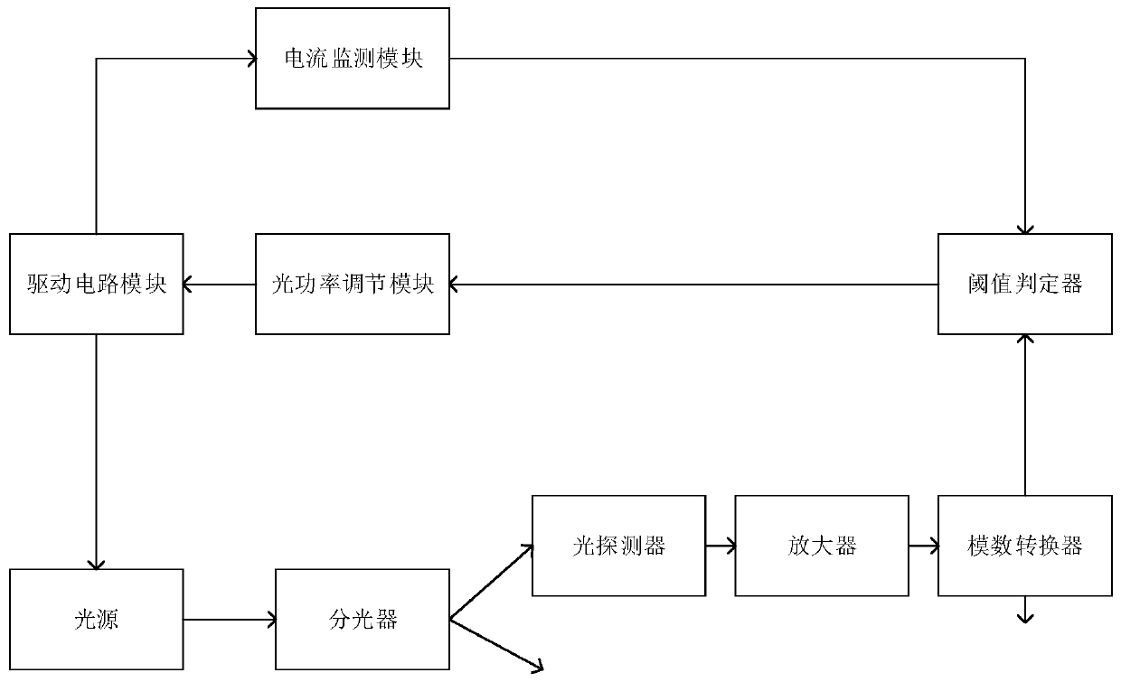
[0053] Such as figure 1 As shown, it is a schematic structural diagram of an optical power control device for optical fiber vibration sensing in an embodiment of the present invention. The light output port of the light source is connected to the optical splitter through the vibration sensing fiber, and the optical splitter converts the outgoing light of the light source Divided into at least tw...


PUM


Abstract

The invention discloses an optical power control method used for optical fiber vibration sensing. The optical power control method comprises the steps that step one: receiving end optical power is acquired; step two: whether the receiving end optical power is lower than a preset normal optical power threshold is judged, the process turns to the step four if the judgment result is yes, or the process turns to the step one; step four: the present value of an optical power regulating module increases first preset regulating step length, wherein the present value of the optical power regulating module is used for regulating driving current of a light source; step five: whether the driving current of the light source exceeds the upper limit of the rated working current of the light source is judged, the process turns to the step eight if the judgment result is yes, or the process turns to the step one; and step eight: the present value of the optical power regulating module decreases second preset regulating step length and the process turns to the step one. The method of obtaining the relatively stable receiving optical power at the photodetector end in a low cost vibration sensing system is provided. Besides, the invention also provides an optical power control device used for optical fiber vibration sensing.

Description

technical field [0001] The invention belongs to the technical field of optical fiber sensing, and more specifically relates to an optical power control method and device for optical fiber vibration sensing. Background technique [0002] In general fiber optic vibration sensing systems, the design of fixed output light power is generally adopted. Using a fixed output light power can ensure the stability of the output power of the light source. However, during the installation and deployment of the fiber optic vibration sensing system, different coupling forms of the sensing fiber and the length of the sensing fiber will cause different degrees of loss of the optical signal in the fiber link. In this way, even if two sets of optical fiber vibration sensing devices with exactly the same outgoing optical power, it is difficult to obtain the same incident (received) optical power in different installation and deployment environments. [0003] Received optical power is an import...

Claims


Application Information

Patent Timeline
Patent Type & Authority Patents(China)
IPC IPC(8): G01H9/00
CPCG01H9/004
Inventor 王雪峰曹孟辉
Owner 宏安集团有限公司
Why Eureka
Try Eureka