Low-noise power capacitor using damping steel plates

A power capacitor and low-noise technology, which is applied in the field of noise control of high-voltage power equipment, can solve the problems of unsatisfied, no substantial reduction in noise, etc., and achieve the effects of reducing bottom vibration, bottom noise, and low density

Inactive Publication Date: 2017-06-30
GUILIN UNIV OF ELECTRONIC TECH
View PDF6 Cites 3 Cited by
  • Summary
  • Abstract
  • Description
  • Claims
  • Application Information

AI Technical Summary

Problems solved by technology

[0004] In order to solve the bottom noise problem, in 2011, Dr. Wu Peng of Xi'an Jiaotong University proposed a double-bottom structure to reduce the noise on the bottom of the power capacitor in "High Voltage DC Converter Station AC Filter Capacitor Noise Reduction Measures". In 2013, Zuo Qianglin's "HVDC Use Development of Low-noise Capacitors", through a large number of experiments and conclusions, it is concluded that adding sound insulation chambers at both ends of the capacitor element group bottom and cover is a more effective solution for capacitor noise control, and also verified the effectiveness of the double-bottom structure proposed by Dr. Wu Peng. At the same time, a certain noise reduction effect has been achieved in engineering applications, but it has not yet met the requirements of the environmental department for the noise level of capacitors to be lower than 55dB.
[0005] Dr. Wu Peng from Xi'an Jiaotong University also studied double-bottom capacitors, which achieved a significant noise reduction effect and was put into use in Shanghai Fengxian Converter Station. However, compared with the actual effect, it has not yet met the national department's requirement that the noise level of capacitors be lower than 55dB. requirements, there is no substantial reduction in the noise in the low-to-medium frequency region radiated from the bottom of the capacitor

Method used


Image

  • Low-noise power capacitor using damping steel plates
  • Low-noise power capacitor using damping steel plates
  • Low-noise power capacitor using damping steel plates

Examples


Embodiment

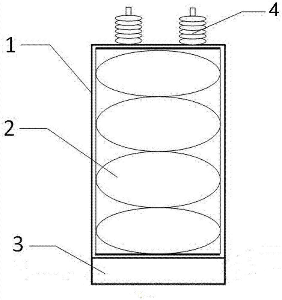
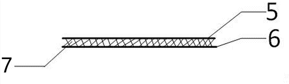
[0022] Such as figure 1 , figure 2 As shown, a low-noise power capacitor using a damping steel plate includes a capacitor case 1, a core 2, a bushing 4 and a sound insulation chamber 3, the bushing 4 is set on the top of the capacitor case 1, and the core 2 is set on the capacitor case 1 Inside, the sound insulation cavity 3 is arranged at the bottom of the capacitor case 1; the sound insulation cavity 3 is a closed cavity structure composed of two layers of steel plates inside and outside, and a damping material 7 is arranged between the outer layer steel plate 6 and the inner layer steel plate 5 , forming a closed cavity structure with three layers.

[0023] The closed cavity structure is fixed to the bottom of the capacitor by welding.

[0024] The inside of the closed cavity is air.

[0025] The thickness of the air layer inside the closed cavity is 20mm-30mm.

[0026] The steel plate is a stainless steel plate with a thickness of 0.5 mm and an area density of 3.95 kg...


PUM


Abstract

The invention discloses a low-noise power capacitor using damping steel plates. The low-noise power capacitor comprises a capacitor shell, a core, a casing, and a sound insulation cavity. The casing is arranged on the top of the capacitor shell. The core is arranged inside the capacitor shell. The sound insulation cavity is arranged at the bottom of the capacitor shell. The sound insulation cavity is a closed cavity structure composed of inner and outer steel plates. A damping material is arranged between the outer steel plate and the inner steel plate to form a three-layer closed cavity structure. By making use of low density, sound insulation, noise reduction, vibration absorption, high strength, high specific rigidity and other advantages of the damping steel plates, vibration at the bottom of the power capacitor can be reduced. The closed cavity formed by welding the damping steel plates is used to insulate sound in the main contribution frequency band of noise, so that vibration at the bottom of the power capacitor is reduced, and actual engineering requirements are met.

Description

technical field [0001] The invention belongs to the technical field of noise control of high-voltage power equipment, in particular to a low-noise power capacitor using a damping steel plate. [0002] technical background [0003] With the continuous improvement of the DC transmission level and the increase of the transmission power, the noise pollution generated by the shunt capacitor device is becoming more and more serious, which has far exceeded the field standard set by the national environmental department. Therefore, the audible noise generated by the filter capacitor device Noise pollution has become a problem that cannot be ignored. It has been proved by experiments that the noise frequency generated by the operation of power capacitors is 100HZ, 500HZ, 600HZ, 800HZ, 1100HZ, 1150HZ, 1200HZ, 1250HZ and other medium and low frequencies, and the generated noise mainly points to the bottom and top of the power capacitor. [0004] In order to solve the bottom noise probl...

Claims


Application Information

Patent Timeline
Patent Type & Authority Applications(China)
IPC IPC(8): H01G4/002H01G4/224
CPCH01G4/002H01G4/224
Inventor 周峰刘夫云
Owner GUILIN UNIV OF ELECTRONIC TECH
Why Eureka
Try Eureka