Broadband circularly-polarized waveguide antenna and antenna array thereof

A circularly polarized wave and circularly polarized technology, used in antenna arrays, leaky waveguide antennas, and individually powered antenna arrays, etc., can solve the problems of narrow operating bandwidth, narrow antenna operating bandwidth, insufficient specific bandwidth, etc., and achieve widening work. Bandwidth, easy processing, simple structure effect

Active Publication Date: 2017-06-30
CHINA ELECTRONIC TECH GRP CORP NO 38 RES INST
View PDF7 Cites 20 Cited by
  • Summary
  • Abstract
  • Description
  • Claims
  • Application Information

AI Technical Summary

Problems solved by technology

[0006] US Patent US5579019 slotted waveguide leaky wave antenna (Masahiro Uematsu, Takashi Ojima, etc., slotted leaky waveguide array antenna) and US7436371B1 low-loss low-profile dual-polarized waveguide In the crescent slot antenna array (Lee M. Paulson, Cod Ripis, etc., Lee M.Paulsen, Cedar Rapids, etc, waveguide crescent slot array for low-loss, low-profile dual-polarization antenna), There is a problem of broadband working beam pointing dispersion and reduced efficiency
[0007] Zhang Hongtao, Wang Wei and others proposed a circularly polarized waveguide standing wave antenna (Chinese patent, patent number: 200910185457.3), which is limited by the characteristics of the waveguide standing wave slot array, that is, the more units, the narrower the working bandwidth, and this The axial ratio bandwidth of this circularly polarized waveguide antenna is relatively narrow, and the 3dB axial ratio bandwidth is less than 3%.
[0008] Wang Wei, Qi Meiqing, Zhang Hongtao and others proposed a circularly polarized antenna (Chinese patent, patent number: 201310454644.3), in which the circularly polarized working mode is realized by opening two kinds of slots in the ridge waveguide, but the circularly polarized waveguide antenna It is also limited by the characteristics of the waveguide standing wave slot array, that is, the more the number of elements, the narrower the working bandwidth of the antenna
[0009] Zhang Hongtao, Wang Wei and others proposed a novel circularly polarized waveguide slot antenna and its design method (Chinese patent, patent application number: 201510012239.5), using two kinds of radiation slots on the "convex" waveguide to realize the circular pole However, the working bandwidth of the circularly polarized antenna is also limited by the number of units, that is, the more the number of units, the narrower the working bandwidth

Method used


Image

  • Broadband circularly-polarized waveguide antenna and antenna array thereof
  • Broadband circularly-polarized waveguide antenna and antenna array thereof
  • Broadband circularly-polarized waveguide antenna and antenna array thereof

Examples


Embodiment 1

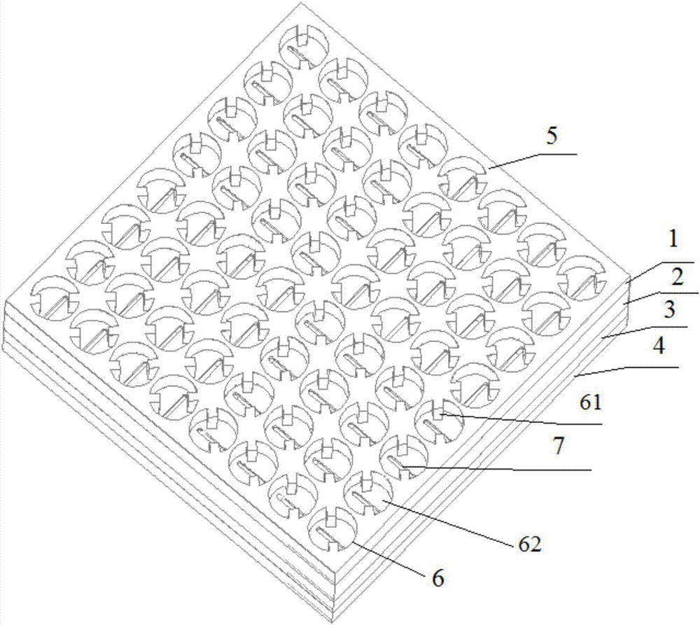
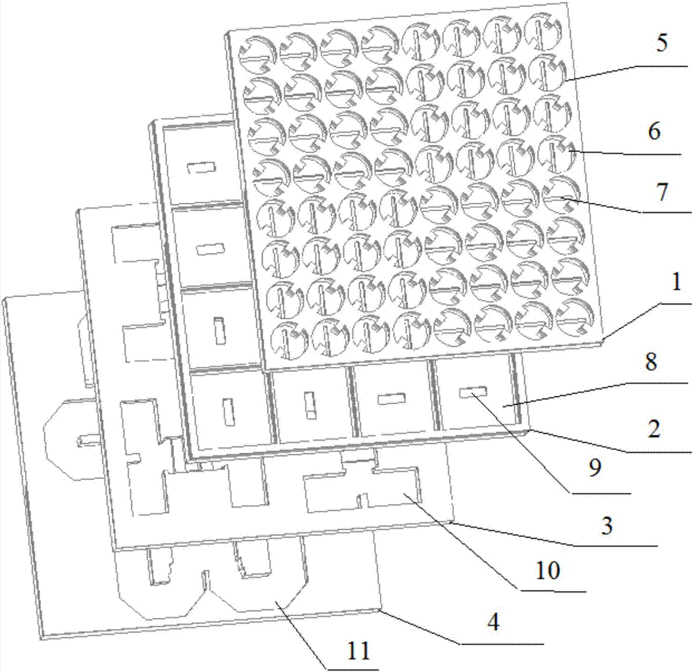
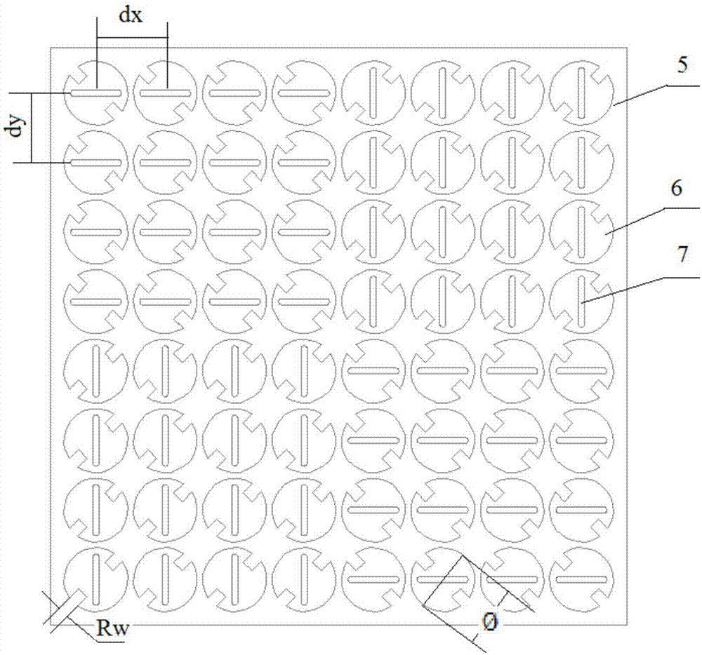
[0041] see again image 3 and Figure 4 , first define: the diameter of the circular ridge opening waveguide 6 is The height is Ch, the width of the ridge is Rw, and the height of the ridge is Rh; the length of the coupling feeding straight slot 7 is Ls, the width is Ws, and the metal wall thickness is t; the length of the rectangular cavity 8 is a, and the width is b, The height is h; the length of the coupling feeding straight slot 2 9 is Lc, and the width is Wc.

[0042] A preferred embodiment of the present invention is a 64-element broadband circularly polarized waveguide antenna according to the uniformly distributed X-band, adopting a standard rectangular waveguide 12 center feed, see Figure 1 to Figure 5 shown. The working center frequency is f0, the lower side frequency is fL, and the upper side frequency is fH. In this embodiment, 10, 9.2, and 10.8 GHz are selected respectively.

[0043] The broadband circularly polarized waveguide antenna is mainly composed of...

Embodiment 2

[0053] When forming an array, the antenna in Embodiment 1 can be used as a basic module, and a large planar broadband circularly polarized waveguide array antenna can be expanded through a power division network. The wideband circularly polarized waveguide antenna array of the present invention includes N*N wideband circularly polarized waveguide antennae, where N is a positive integer.

[0054] Another preferred embodiment of the present invention is Figure 9 ~ Figure 10 As shown, the broadband circularly polarized waveguide antenna array consists of 4 figure 1 The 64-element broadband circularly polarized waveguide antenna shown is shifted and fed by a waveguide power divider divided into four to form a larger broadband circularly polarized waveguide antenna array.


PUM


Abstract

The invention discloses a broadband circularly-polarized waveguide antenna and an antenna array thereof. The antenna comprises a radiation layer, a cavity layer, a feed network layer and a circularly-polarized network layer, wherein the radiation layer, the cavity layer, the feed network layer and the circularly-polarized network layer are sequentially stacked to form a multilayer stacked structure. One side, backing on to the cavity layer, of the radiation layer is provided with 8*8 radiation units which are arranged in an array. Each radiation unit comprises a circular ridge opening waveguide with two symmetric ridges, and a first coupling feed straight gap which is disposed on a bottom wall of the circular ridge opening waveguide, wherein the two ridges are located at two opposite sides of the first coupling feed straight gap, and the vertical connection line of the two ridges and the first coupling feed straight gap form a 45-degree inclined angle. The 8*8 radiation units are divided into four radiation unit groups, and each radiation unit group comprises 4*4 radiation units which are arranged in an array. One radiation unit group is taken as a fixed point reference, and other three radiation unit groups sequentially rotate 90 degrees, 180 degrees and 270 degrees anticlockwise or clockwise.

Description

technical field [0001] The invention relates to an antenna and an antenna array thereof in the fields of satellite communication and microwave communication, in particular to a broadband circularly polarized waveguide antenna and an antenna array thereof. Background technique [0002] In recent years, with the vigorous development of satellite communications, antennas used in satellite broadcasting, television, communication and data transmission systems have developed rapidly, and the demand for various antennas has also increased rapidly, which has promoted their development. For example, for direct broadcast satellite (DBS) communication systems, low-profile, high-efficiency antenna systems are required to increase the G / T value of the system (G is the gain of the antenna system; T is the noise temperature of the antenna system) to increase the antenna and Data rate for satellite communications. Moreover, the effective aperture of the antenna is limited by the scanning v...

Claims


Application Information

Patent Timeline
Patent Type & Authority Applications(China)
IPC IPC(8): H01Q15/24H01Q13/20H01Q21/00H01Q21/06
CPCH01Q13/20H01Q15/24H01Q21/0006H01Q21/061
Inventor 张洪涛汪伟金谋平孙立春郑治杨诚
Owner CHINA ELECTRONIC TECH GRP CORP NO 38 RES INST
Why Eureka
Try Eureka