A new efficient installation method for ballast groove slabs of steel truss bridges

An installation method and channel plate technology, applied in bridges, bridge parts, bridge construction, etc., can solve problems such as the inability to use large mechanical equipment, the heavy weight of a single ballast channel plate, and the limited working space of steel truss girders, etc., to achieve large Promote value, improve efficiency, and technically feasible effects

Active Publication Date: 2018-07-27
STEEL STRUCTURE CONSTR CO LTD OF CHINA TIESUU CIVIL ENG GRP
View PDF6 Cites 0 Cited by
  • Summary
  • Abstract
  • Description
  • Claims
  • Application Information

AI Technical Summary

Problems solved by technology

[0004] 1. The ballast trough is a special-shaped cross-section. There are many shear nail grooves reserved for a ballast trough. The steel bars in the shear nail grooves are dense and dense. When installing, each shear nail on the longitudinal and beam needs to be Pass through the reinforcement grid of the reserved groove of the ballast slab, requiring high matching accuracy
[0005] 2. The weight of a single ballast groove slab is heavy, and the internal working space of the steel truss girder is limited, so large-scale mechanical equipment cannot be used. The upper plane of the steel truss girder is equipped with parallel and horizontal joints at each node, and it is impossible to install the steel truss girder on the upper plane. Perform continuous installation work

Method used


Image

  • A new efficient installation method for ballast groove slabs of steel truss bridges
  • A new efficient installation method for ballast groove slabs of steel truss bridges

Examples


Embodiment Construction

[0029] See attached picture.

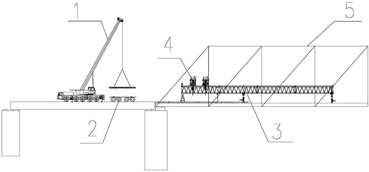
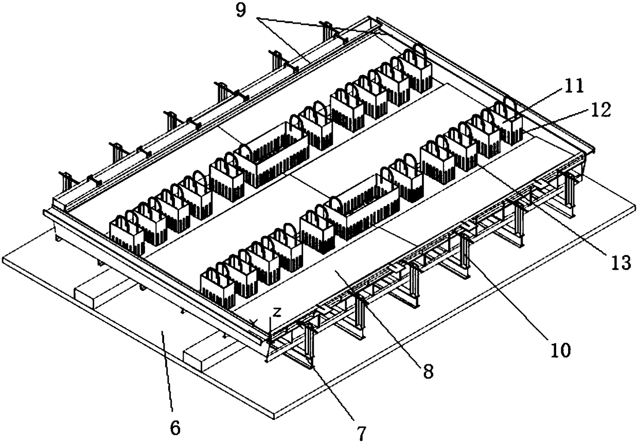
[0030] A new type of efficient installation method for ballast slabs of steel truss bridges, based on the steel truss bridge deck adopting longitudinal and beam structure systems, prefabricated ballast slabs are installed in sections on the longitudinal and transverse beams, prefabricated ballast slabs When the shear nail groove is reserved at the corresponding position, the shear nail groove and the longitudinal beam are combined with the principle of joint stress after pouring concrete through the cylindrical head flexible shear nail arranged on the top surface of the longitudinal beam at the shear nail groove; it is characterized in that: Specific steps are as follows:

[0031] 1) First, design and process the corresponding ballast slab prefabricated formwork according to the section form of the ballast slab. During the prefabrication process of the ballast slab, ensure the accuracy of the position of the steel bars and the quality of concrete...


PUM


Abstract

The invention discloses a novel efficient mounting method for ballast trough plates of a steel truss girder bridge. Based on a deck of the steel truss girder bridge, a longitudinal and cross girder structure system is adopted; the prefabricated ballast trough plates are mounted on longitudinal and transverse girders in section; and shear nail grooves are reserved in the corresponding positions when the ballast trough plates are prefabricated, and the joint force bearing principle is combined in the shear nail grooves and the longitudinal girders after concrete is poured through cylinder head flexible shear nails arranged on the top faces of the longitudinal girders. A vertical lifting device is utilized to hoist the ballast trough plates to a girder transporting gun carriage; the gun carriage transports to the position between two main girders of a frame plate machine and below overhead cranes along the deck; after the ballast trough plates are lifted up on the gun carriage through the overhead cranes, the positions are adjusted precisely through longitudinal moving of the overhead cranes, transverse moving of lifting hooks of the overhead cranes and overall transverse moving of the frame plate machine, slow drop-hook is conducted, and the ballast trough plates are mounted in the designed positions. Steel bar grids penetrate through the steel girder shear nails in the reserved shear nail grooves of the ballast trough plates and then are mounted in place. The construction problem of mounting the prefabricated ballast trough plates with complex cross sections is solved.

Description

Technical field: [0001] The invention relates to the technical field of bridge construction, and mainly relates to a novel efficient installation method for ballast groove slabs of steel truss bridges, which is especially suitable for the installation and construction of prefabricated bridge decks. Background technique: [0002] The steel truss bridge deck adopts the longitudinal and transverse beam structure system. Prefabricated ballast slabs are installed in sections above the longitudinal and transverse beams. When the ballast slabs are prefabricated, shear nail slots are reserved at the corresponding positions. The trough and the longitudinal beam are combined to bear the force after pouring concrete through the cylindrical head flexible shear nails arranged on the top surface of the longitudinal beam. [0003] Due to the heavy weight of a single ballast slab, the internal working space of the steel truss girder bridge is limited, the installation accuracy is high, the ...

Claims


Application Information

Patent Timeline
Patent Type & Authority Patents(China)
IPC IPC(8): E01D21/00E01D19/12
CPCE01D19/125E01D21/00
Inventor 张建金方继徐波曹晗张伟李亚飞江明慧张庆发吴孝万丁仕洪刘果
Owner STEEL STRUCTURE CONSTR CO LTD OF CHINA TIESUU CIVIL ENG GRP
Why Eureka
Try Eureka