Wheel type explosive motor

A technology of internal combustion engine and wheel type, applied in the direction of internal combustion piston engine, combustion engine, machine/engine, etc., can solve the problems of high operating noise, high manufacturing cost, poor reliability and durability, etc., and achieve low vibration and noise, large Development advantage, effect of small size

Inactive Publication Date: 2017-07-04
秦阳林
View PDF0 Cites 2 Cited by
  • Summary
  • Abstract
  • Description
  • Claims
  • Application Information

AI Technical Summary

Problems solved by technology

[0003] 1. In order to convert the linear motion of the piston into rotary motion, it is necessary to set up the crank connecting rod mechanism, steam distribution structure, timing belt, camshaft, rocker arm and other components, resulting in a large volume and weight of the engine, and its manufacturing cost is relatively high. high;
[0004] 2. The piston reciprocates many times

Method used


Image

  • Wheel type explosive motor
  • Wheel type explosive motor
  • Wheel type explosive motor

Examples


Embodiment 1

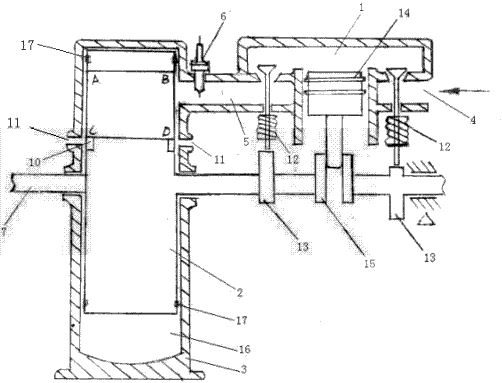
[0034] Such as figure 1 As shown, a wheel-type internal combustion engine includes a mixed gas compression chamber 1, a transmission wheel 2 and a housing 3; one end of the mixed gas compression chamber 1 is provided with an inlet 4 for sending mixed gas into its interior, and the mixed gas The other end of the steam compression chamber 1 is provided with an outlet 5 for discharging the compressed mixed steam inside, and the outlet 5 communicates with the inside of the housing 1, and the inlet 4 or the outlet 5 is provided with a Switch valve 12. One end of the rotating shaft 7 passes through the housing 3 and extends towards the direction of the mixed gas compression chamber 1, and the rotating shaft 7 is provided with a valve 12 corresponding to the top pressure to switch the inlet 4 or the The two cams 13 of the outlet 5, the cams 13 are respectively located on the rotating shaft 7 and corresponding to the position of the inlet 4 and the position corresponding to the outle...

Embodiment 2

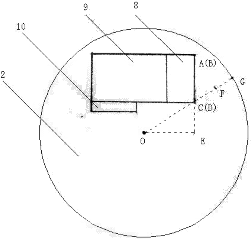
[0045] Such as Figure 6 As shown, the cavity 8 is designed as a through hole of the fan structure through which the transmission wheel 2 axially penetrates, and the elimination mechanism 9 is designed as a fan structure matching the cavity 8, and one end with a circular arc surface faces the cavity The opposite side of 8 extends, and all the other structures are identical with embodiment one.

[0046] The elimination mechanism 9 is a fan structure, and its two sides are also two opposite slopes, and the work done on the elimination mechanism 9 after the explosion of the mixed gas can also be offset. In addition, because the cavity 8 is a fan structure matched with the elimination mechanism 9, the side of the cavity 8 is the force arm of the opposite side of the elimination mechanism 9 after the explosion of the mixed gas (the force arm is image 3 OF in, wherein F is the midpoint of CG; the moment arm in the first embodiment is OE, according to the right triangle theorem, it...


PUM


Abstract

The invention relates to a wheel type explosive motor, comprising a mixed gas compression chamber, a driving wheel, and a housing. One end of the mixed gas compression chamber is provided with an inlet through which mixed gas is sent into the mixed gas compression chamber, and the other end of the mixed gas compression chamber is provided with an outlet which discharges the mixed gas which is compressed in the mixed gas compression chamber. The outlet is communicated with the internal of the housing. The outlet is internally provided with a sparking plug which lights the compressed mixed gas. The driving wheel is rotatably arranged in the housing through a rotating shaft. The driving wheel is provided with a cavity used for explosion working after the mixed gas is ignited. The cavity is internally provided with an eliminating mechanism which makes the mixed gas apply work on one side of the cavity after the mixed gas explodes to realize rotation of the driving wheel and output torque through rotation of the rotating shaft. Beneficial effects are that on one aspect, the wheel type explosive motor rotates to apply work on one direction all along, explosion expansion power is maximized, and on the other hand, the size of the motor is relatively small, weight is relatively light, and vibration and noise are relatively low, and the motor has great development advantages.

Description

technical field [0001] The invention relates to the field of internal combustion engines, in particular to a wheeled internal combustion engine. Background technique [0002] Most of the existing engines are reciprocating, that is, the piston performs a reciprocating linear motion in the cylinder during work. This reciprocating engine has the following defects: [0003] 1. In order to convert the linear motion of the piston into rotary motion, it is necessary to set up the crank connecting rod mechanism, steam distribution structure, timing belt, camshaft, rocker arm and other components, resulting in a large volume and weight of the engine, and its manufacturing cost is relatively high. high; [0004] 2. The piston reciprocates many times before doing work once, which wastes a lot of combustion expansion power; [0005] 3. The movement of the piston itself forms a reciprocating vibration source, and the operating noise is relatively large; [0006] 4. Mechanical componen...

Claims


Application Information

Patent Timeline
IPC IPC(8): F02B53/00
CPCF02B53/00Y02T10/12
Inventor 秦阳林
Owner 秦阳林
Why Eureka
Try Eureka