Automatic overturning mechanism for welding fixture

An automatic flipping and welding fixture technology, which is applied in welding equipment, auxiliary welding equipment, welding/cutting auxiliary equipment, etc., can solve the problems of difficult equipment cleaning and maintenance, expensive manipulators, and poor running stability, so as to save production energy consumption, Takes up little space and ensures stability

Inactive Publication Date: 2017-07-07
TIANJIN WEIKE WODE TECH
View PDF0 Cites 4 Cited by
  • Summary
  • Abstract
  • Description
  • Claims
  • Application Information

AI Technical Summary

Problems solved by technology

However, the price of the manipulator is relatively expensive, the production cost required by the enterprise is relatively high, and the working process requires a lot of electric energy and high energy consumption; in addition, the traditional turning mechanism takes up a large space, has poor running stability, and is difficult to clean and maintain the equipment.

Method used


Image

  • Automatic overturning mechanism for welding fixture
  • Automatic overturning mechanism for welding fixture

Examples


Embodiment 1

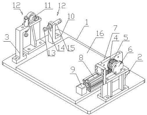
[0014] During installation, at first a moisture-proof pad 16 is set on the workbench 1, and a driving shaft mounting frame 2 and a driven shaft mounting frame 3 are arranged on both sides of the moisture-proof pad 16, and a rack 4 is arranged on the driving shaft mounting frame 2, and the rack 4 and the gear 5 meshing, the drive shaft bushing 6 is set on the gear 5, the assembly plate 7 is set on the outside of the rack 4, one end of the rack 4 is connected to one end of the nitrogen cylinder 8, and the other end of the nitrogen cylinder 8 is connected to the solenoid valve 9, from Driven shaft mounting frame 3 is provided with driven shaft shaft sleeve 3, and one side of driven shaft mounting frame 3 is provided with buffer device mounting frame 10, buffer device mounting frame 10, driving shaft mounting frame 2, driven shaft mounting frame 3 are all A buffer device 12 is provided. The buffer device 12 is composed of a metal contact 13, a compression rod 14 and a nitrogen cyli...

Embodiment 2

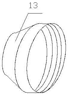
[0016] When in use, the electromagnetic valve 9 is activated by the PLC controller, the nitrogen cylinder 8 pushes the rack 4, and the rack 4 drives the gear 5 meshing with the rack 4 to rotate during the movement, and the gear 5 is provided with a driving shaft sleeve 6 to drive The shaft sleeve 6 is connected with the welding jig through a bearing, that is, the rotation of the gear 5 drives the jig to rotate, and the workpiece contacts the metal contact 13 when rotating, and the metal contact 13 pushes the telescopic rod 14, and the telescopic rod 14 moves in the nitrogen cylinder 15 to Buffer the inertial force of the workpiece rotation to avoid bumping or shaking, and the metal contact 13 is provided with threads inside, the metal contact 13 is connected to the telescopic rod 14 through the thread, and can be disassembled when the appearance of the metal contact is damaged. replace.


PUM


Abstract

The invention provides an automatic turning mechanism for a welding fixture, which is characterized in that it includes a workbench, a driving shaft mounting frame, a driven shaft mounting frame, etc., a moisture-proof pad is arranged on the workbench, and the two sides of the moisture-proof pad are arranged There is a driving shaft mounting frame and a driven shaft mounting frame, the driving shaft mounting frame is provided with a rack, the outside of the rack is provided with an assembly plate, the rack is meshed with a gear, and the gear is provided with a drive Shaft sleeve. The invention uses a nitrogen cylinder to push the rack to drive the active gear meshed with the rack to rotate to drive the fixture to turn over, replacing the existing way of turning over the manipulator, which saves electric energy, is convenient to operate, fast in response, strong in operation stability, and low in production cost; The inside of the contact is provided with a thread, which is connected with compression through the thread. When the metal contact is damaged or the surface is uneven, it can be disassembled and replaced without replacing the buffer device, which saves energy consumption for production, and reduces cleaning and maintenance costs.

Description

technical field [0001] The invention relates to the technical field of mechanical processing, in particular to an automatic turning mechanism of a welding fixture. Background technique [0002] In the machinery manufacturing industry, in order to improve the degree of welding automation and reduce the influence of errors caused by welding deformation and secondary clamping on the quality of automatic welding, manipulators are now used instead of manual manual flipping processes to reduce labor intensity and improve processing and production efficiency. Automation and intelligence. However, the price of the manipulator is relatively expensive, the production cost required by the enterprise is high, and the working process requires a lot of electric energy and high energy consumption; in addition, the traditional turning mechanism takes up a large space, has poor operation stability, and is difficult to clean and maintain the equipment. Contents of the invention [0003] Ac...

Claims


Application Information

Patent Timeline
Patent Type & Authority Applications(China)
IPC IPC(8): B23K37/04B23K37/047
CPCB23K37/0443B23K37/047
Inventor 董英王祥
Owner TIANJIN WEIKE WODE TECH
Why Eureka
Try Eureka