Catalytic cracking oil slurry pretreatment system and pretreatment method by utilization of system

A technology for catalytic cracking oil slurry and pretreatment, which is applied in the treatment of hydrocarbon oil, multi-stage series-connected refining process treatment, petroleum industry, etc. The effect of high extraction efficiency and improved removal efficiency

Active Publication Date: 2017-07-07
ENERGY & ENVIRONMENT RES INST OF HEILONGJIANG PROVINCE
View PDF5 Cites 14 Cited by
  • Summary
  • Abstract
  • Description
  • Claims
  • Application Information

AI Technical Summary

Problems solved by technology

[0010] The present invention aims to solve the technical problem of low catalyst powder removal efficiency during catalytic cracking oil slurry, and proposes a catalytic cracking oil slurry pretreatment system and a pretreatment method using the system

Method used


Image

  • Catalytic cracking oil slurry pretreatment system and pretreatment method by utilization of system
  • Catalytic cracking oil slurry pretreatment system and pretreatment method by utilization of system
  • Catalytic cracking oil slurry pretreatment system and pretreatment method by utilization of system

Examples


specific Embodiment approach 1

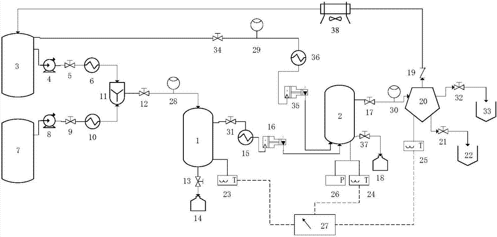
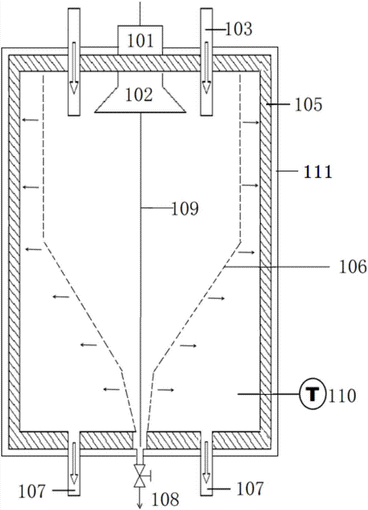
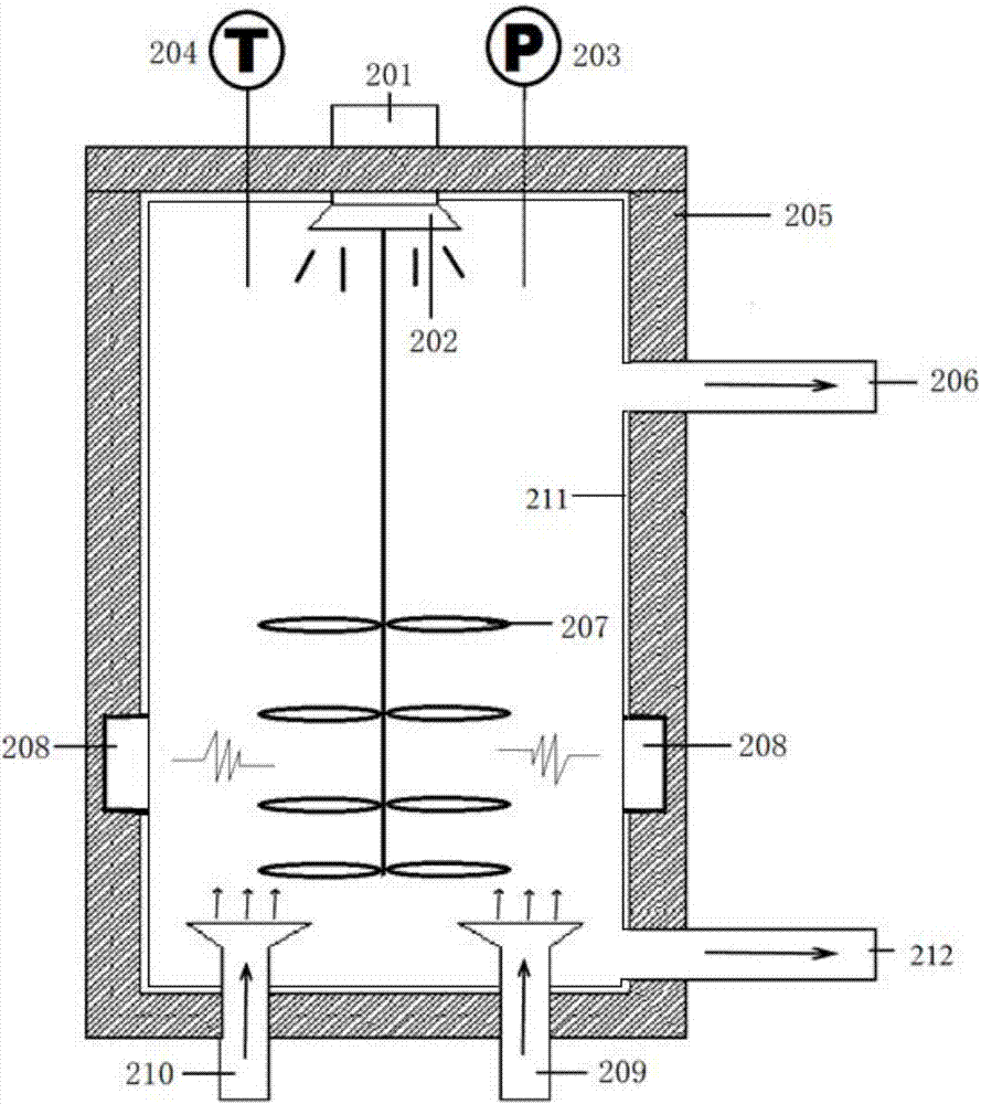
[0037] Specific Embodiment 1: In this embodiment, a catalytic cracking oil slurry pretreatment system includes a solvent tank 3, a catalytic cracking oil slurry tank 7, a mixer 11, an ultrasonic centrifugal separation device 1, an ultrasonic and microwave-enhanced supercritical extraction device 2, a separation Device 20, solid particle collection tank 14, heavy component collector 22 and light component collector 33;

[0038] Wherein, an outlet of the solvent tank 3 communicates with an inlet of the mixer 11, and a first high-pressure pump 4, a first screw valve 5 and a first heating system 6 are arranged between the solvent tank 3 and the mixer according to the flow direction of the medium, and the catalytic The outlet of the cracked oil slurry tank 7 communicates with the other inlet of the mixer 11, and a second high-pressure pump 8, a second screw valve 9 and a second heating device are arranged between the catalytic cracked oil slurry tank 7 and the mixer 11 according to ...

specific Embodiment approach 2

[0042] Embodiment 2: The difference between this embodiment and Embodiment 1 is that the ultrasonic centrifugal separation device 1 is connected to the first thermocouple, the ultrasonic synergistic microwave enhanced supercritical extraction device 2 is connected to the second thermocouple, and the separator 20 is connected to the third thermocouple. I. Others are the same as in the first embodiment.

specific Embodiment approach 3

[0043] Embodiment 3: This embodiment differs from Embodiment 1 or Embodiment 2 in that: the first thermocouple 23 , the second thermocouple 24 and the third thermocouple 25 are all connected to an electronic temperature control system 27 . Others are the same as in the first or second embodiment.


PUM

PropertyMeasurementUnit
particle diameteraaaaaaaaaa
particle sizeaaaaaaaaaa
densityaaaaaaaaaa

Abstract

A catalytic cracking oil slurry pretreatment system and a pretreatment method by the utilization of the system are disclosed. The invention relates to the field of comprehensive utilization of catalytic cracking oil slurry, specifically to a catalytic cracking oil slurry pretreatment device, a system thereof and a pretreatment method. The invention aims to solve the problem of low efficiency during the process of catalytic cracking oil slurry pretreatment. The system comprises a solvent tank, a catalytic cracking oil slurry tank, a mixer, an ultrasonic centrifuge device, an ultrasound-assisted microwave-enhanced supercritical extraction device, a separator, a solid particle gathering tank, a heavy components collector and a light components collector. Through a raw material mixing unit, a solid-liquid separation unit, a solvent extraction unit, a components separation unit and a solvent recovery unit, catalyst granules and oil slurry are separated, and separation of light and heavy components of oils and precision cutting extraction are realized. The method has advantages of simple process equipment and good separation effect.

Description

technical field [0001] The invention relates to the field of comprehensive utilization of catalytic cracking oil slurry, in particular to a pretreatment device, system and pretreatment method of catalytic cracking oil slurry. Background technique [0002] As the global petroleum resources become more and more heavy, catalytic cracking (Fluid catalytic cracking, FCC) is becoming more and more important as an advanced technology for heavy oil processing. The annual processing volume of catalytic cracking in my country exceeds 150 million tons, and the output of oil slurry accounts for about 5% to 10% of the treatment volume of catalytic cracking. The output of oil slurry, a by-product of catalytic cracking, also increases year by year. The properties of catalytic cracking oil slurry are very special. The components are mainly polycyclic aromatic hydrocarbons, generally without long alkyl side chains, and the average relative molecular weight is relatively large, about 500, whi...

Claims


Application Information

Patent Timeline
Patent Type & Authority Applications(China)
IPC IPC(8): C10G53/04
CPCC10G53/04C10G2300/1037C10G2300/201
Inventor 杨光陈松徐晓秋许超张帆
Owner ENERGY & ENVIRONMENT RES INST OF HEILONGJIANG PROVINCE
Why Eureka
Try Eureka