
Cutting machine

A cutting machine and frame technology, applied in the field of fabric cutting equipment, can solve the problems of unsatisfactory cutting quality of multi-layer fabrics, lower mechanical cutting accuracy, and uneven feeding of fabrics, etc., so as to improve cutting quality and facilitate equipment maintenance , the effect of reasonable structure layout

Inactive Publication Date: 2017-07-07
GBOS LASER INC
View PDF16 Cites 18 Cited by
  • Summary
  • Abstract
  • Description
  • Claims
  • Application Information

AI Technical Summary

Problems solved by technology

[0002] With the continuous development of society, the use of automated cutting equipment to cut or cut cotton, denim, felt and other fabrics can greatly improve the processing accuracy and production efficiency of the fabric. Most of the existing fabric cutting equipment is laser cutting and cutting. Mechanical cutting and laser cutting are not ideal for thick or multi-layer fabrics. Laser cutting will generate a lot of smoke and cause air pollution in the factory building. At the same time, laser cutting will cause carbides on the edge of the fabric cutting, which will affect the quality of fabric cutting. , while the cutting efficiency of the existing mechanical cutting machine is relatively slow, and at the same time, the cloth is easily wrinkled due to the influence of the cutter during the cutting process, resulting in the unsmooth feeding of the cloth, which further reduces the accuracy of mechanical cutting

Method used


Image

  • Cutting machine
  • Cutting machine
  • Cutting machine

Examples


Embodiment Construction

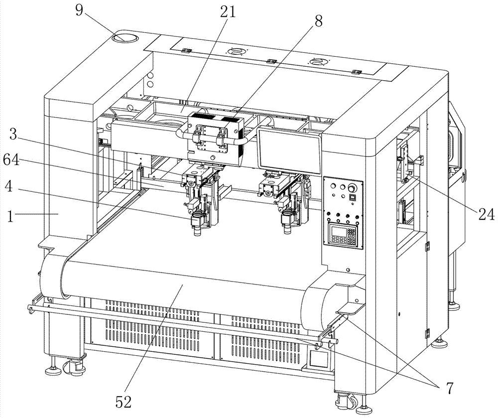
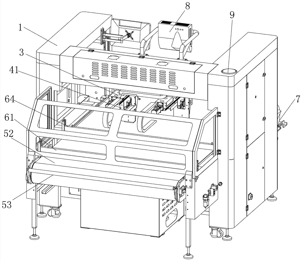
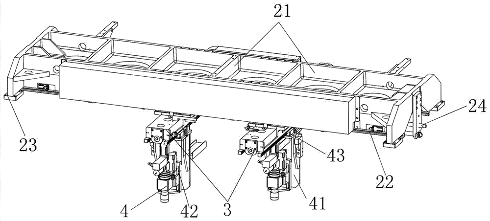
[0028] Refer to attached figure 1 to attach Figure 8 The specific embodiment of the present invention is introduced.

[0029] Such as Figure 1-8 Shown, a kind of cutting machine comprises frame 1 and the feeding device that is arranged on the frame 1; On the frame 1 along the feeding direction of the feeding device, a feeding port, a cutting station and a product collecting station are arranged successively, and the product A waste material recovery device 7 is arranged outside the collecting station, and the frame 1 is provided with a gantry 21 above the cutting station. There is a moving device that drives the knife seat 4 to move in the three-dimensional space, and a traction pressing device and a fixed pressing device are sequentially arranged between the feeding port and the cutting station along the feeding direction. The frame 1 is provided with a projection preview device above the cutting station, and the projection preview device is a projector 8 .

[0030] Suc...


PUM


Abstract

The invention discloses a cutting machine. The cutting machine comprises a frame and a feeding device which is arranged on the frame, wherein a feed inlet, a cutting station and a product collecting station are successively arranged on the frame along the feeding direction of the feeding device; a portal frame is arranged above the cutting station of the frame, the portal frame hoists at least one tool apron for mounting a tool, a mobile device which drives the tool apron to move in a three-dimensional space is arranged between the portal frame and the tool apron, and a traction material pressing device and a fixed pressing device are successively arranged along the feeding direction between the feed inlet and the cutting station. Cloth and a conveyor belt are clamped together and moved through the traction pressing device, so that the cloth in the transfer process is not staggered, and meanwhile, the cloth is tightly pressed to the conveyor belt through the fixed pressing device, so that the cloth cutting consistency and precision are guaranteed, and the problem that the cloth which is cut is easy to be staggered is solved.

Description

technical field [0001] The invention relates to cloth cutting equipment, in particular to a cutting machine. Background technique [0002] With the continuous development of society, the use of automated cutting equipment to cut or cut cotton, denim, felt and other fabrics can greatly improve the processing accuracy and production efficiency of the fabric. Most of the existing fabric cutting equipment is laser cutting and cutting. Mechanical cutting and laser cutting are not ideal for thick or multi-layer fabrics. Laser cutting will generate a lot of smoke and cause air pollution in the factory building. At the same time, laser cutting will cause carbides on the edge of the fabric cutting, which will affect the quality of fabric cutting. , while the cutting efficiency of the existing mechanical cutting machine is relatively slow, and at the same time, the cloth is easily wrinkled due to the influence of the cutter during the cutting process, resulting in the unsmooth feeding...

Claims


Application Information

Patent Timeline
Patent Type & Authority Applications(China)
IPC IPC(8): D06H7/00
CPCD06H7/00
Inventor 刘文
Owner GBOS LASER INC
Learn More