Wedge block type clutch

A clutch and wedge-type technology, applied in the field of clutches, can solve problems such as unsuitable application, energy consumption, and unsuitable use of variable speed transmission systems

Inactive Publication Date: 2017-07-07
郭克亚
View PDF25 Cites 6 Cited by
  • Summary
  • Abstract
  • Description
  • Claims
  • Application Information

AI Technical Summary

Problems solved by technology

2) Since the centrifugal clutch force is proportional to the square of the rotational speed, and the output power changes with the cube of the operating rotational speed, it is not suitable for use in variable speed transmission systems
4) When the prime mover does not reach the rated speed, the centrifugal body will slip relative to the driven part, which will generate frictional heat and consume part of the energy. long place application

Method used


Image

  • Wedge block type clutch
  • Wedge block type clutch
  • Wedge block type clutch

Examples


Embodiment Construction

[0056] The present invention will be described in further detail below according to accompanying drawing and embodiment:

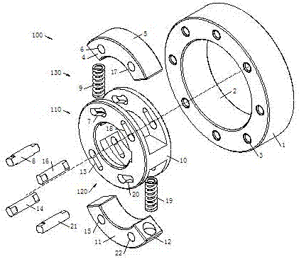
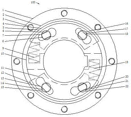
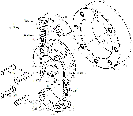
[0057] Such as figure 1 , figure 2 As shown, the sprag clutch 100 of the present invention includes a driving cam 10, a driven element 1, a plurality of centrifugal sprags 4, at least one reset device 130, and radial thrust groups 110 having the same number as the centrifugal sprags 4. The pushing group 110 includes at least one pushing device 7 , and the centrifugal wedge 4 includes at least one friction arc surface 5 . The driving cam 10 and the driven element 1 are radially apart from each other and arranged on the same axis, the driven element 1 is sleeved on the driving cam 10, or the driving cam 10 is sleeved on the driven element 1, and the base circle of the driving cam 10 The radial thrust group 110 with the same number as the centrifugal wedge 4 is arranged in turn around its axis, and the thrusts of the first thrust device 7 and the second th...


PUM


Abstract

The invention discloses a wedge block type clutch which comprises a driving cam, a driven element, a plurality of centrifugal wedge blocks, at least one reset device and radial extending stroke sets the same as the centrifugal wedge blocks in number. The driven element is arranged on the driving cam in a sleeving manner, the radial extending stroke sets are symmetrically arranged on the driving cam, the centrifugal wedge blocks are movably installed on the radial extending stroke sets, and the reset device applies pushing force to the centrifugal wedge blocks to enable the centrifugal wedge blocks and the driven element to keep the non-contact state all the time; and through tiny centrifugal force, the centrifugal wedge blocks are in contact with the driven element, then the radial extending stroke sets push the centrifugal wedge blocks to apply the pushing force in the radial direction, and therefore large torque can be transmitted under the low rotating speed condition. The wedge block type clutch is high in loading capacity and good in impact resistance, and high performance of the single / double-direction clutch can be achieved. The wedge block type clutch can be used for power transmission between a prime motor and a working machine or between a driving element and the driven element in the machine, the separation function and the field of mechanical transmission such as automatic transmissions.

Description

technical field [0001] The invention relates to the technical field of clutches, in particular to a sprag clutch. Background technique [0002] In the prior art, a clutch is a common component in mechanical transmission, which can separate or engage the transmission system at any time. Friction clutch is the most widely used type of clutch. It is basically composed of four parts: active part, driven part, pressing mechanism and operating mechanism; the main, driven part and pressing mechanism are to ensure that the clutch is in the engaged state and can The basic structure of power transmission has smooth engagement and good wear resistance, and the clutch operating mechanism can quickly and completely disengage the clutch at any time, but it is not suitable for applications on equipment that frequently disengages, and there is no overrunning function that will cause inertia loss of power. The one-way clutch is composed of an outer race, an inner race, a cage, a wedge, etc...

Claims


Application Information

Patent Timeline
Patent Type & Authority Applications(China)
IPC IPC(8): F16D41/063F16H37/12F16H57/023F16H57/08
CPCF16D41/063F16H37/12F16H57/023F16H57/08F16H57/082F16H2057/085F16H2057/087
Inventor 郭克亚
Owner 郭克亚
Why Eureka
Try Eureka