
Dual frequency grating measuring device

A measuring device and dual-frequency grating technology, which is applied in the field of dual-frequency grating measuring devices, can solve problems such as difficult installation and adjustment of gratings and reading heads, inconvenient installation and use, and failure of measurement systems, achieving high repeatable measurement accuracy and simple structure , the effect of high measurement accuracy

Active Publication Date: 2019-11-26
SHANGHAI MICRO ELECTRONICS EQUIP (GRP) CO LTD
View PDF11 Cites 0 Cited by
  • Summary
  • Abstract
  • Description
  • Claims
  • Application Information

AI Technical Summary

Problems solved by technology

However, only the detection signal is transmitted through the optical fiber, and the laser light source and the grating read head are placed together, which is bulky and not suitable for use in a compact space; in addition, when the grating is deflected by Rx and Ry angles relative to the read head, the measurement The interference performance of the system will be reduced, resulting in the failure of the measurement system. In this invention, the installation and adjustment of the grating and the reading head are too difficult, and the installation and use are inconvenient

Method used


Image

  • Dual frequency grating measuring device
  • Dual frequency grating measuring device
  • Dual frequency grating measuring device

Examples


Embodiment 1

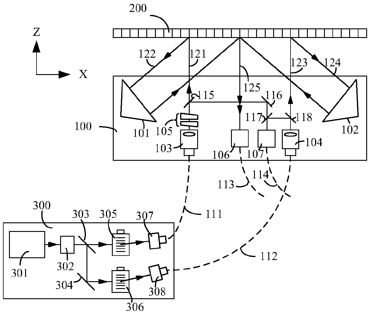
[0031] refer to figure 1 , the dual-frequency grating measurement device of the present invention includes: a grating measurement probe 100 , a grating 200 and a light source module 300 . Wherein, the light source module 300 is used to generate two beams of different frequencies, and transmit the two beams to the grating measuring probe 100 through an optical fiber, and the grating measuring probe 100 is provided with two sets of optical paths for respectively The two beams are received, and the two beams are split, so that one part is transmitted to the detector through the optical fiber, and the other part is projected on the surface of the grating for diffraction and then transmitted to the detector through the optical fiber.

[0032] Continue to refer to figure 1 , the light source module 300 includes a laser 301 , an isolator 302 , a beam splitter, a frequency shifter and a coupler, and the beam splitter includes a beam splitter 303 and a reflector 304 .

[0033] The la...

Embodiment 2

[0052] The difference between this embodiment and Embodiment 1 is that in Embodiment 1 a one-dimensional reflective grating is used, while in this embodiment a two-dimensional reflective grating is used.

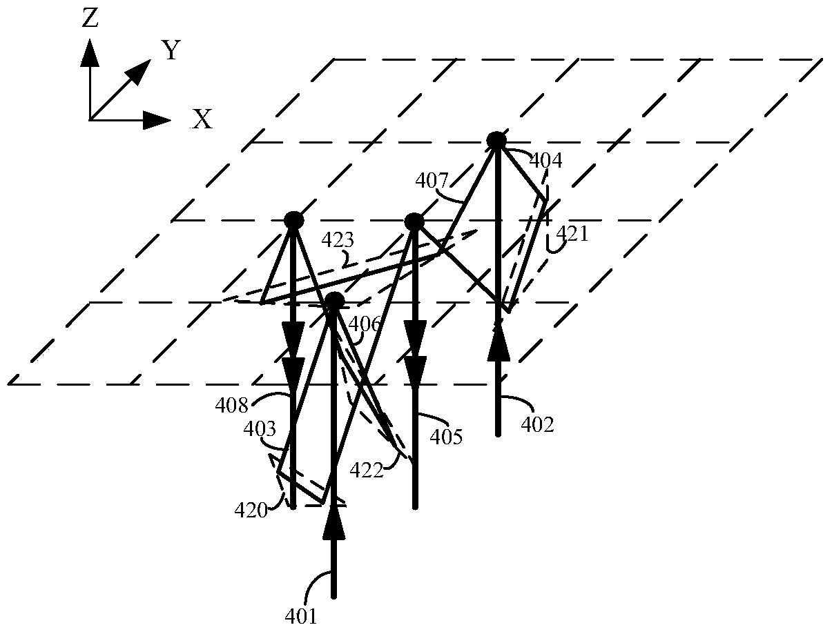
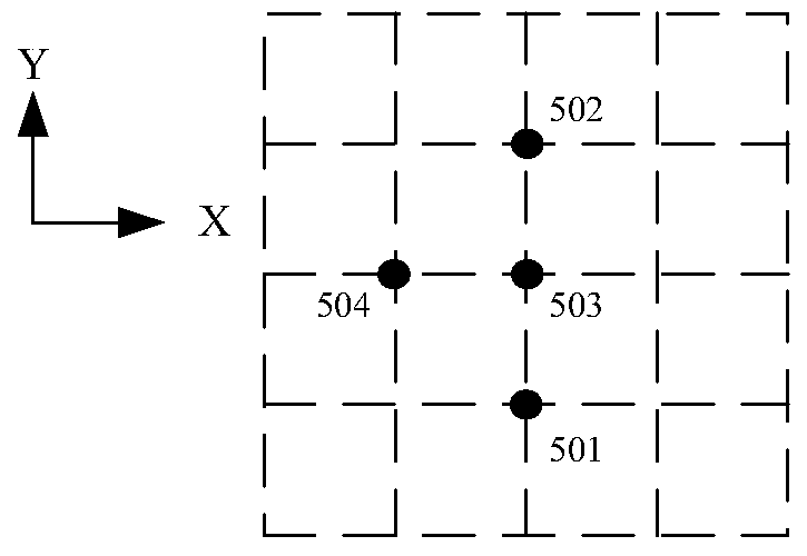
[0053] The layout of the 2D probe is as figure 2 shown. The incident beam 401 with a frequency of Δf1 and the incident beam 402 with a frequency of Δf2 undergo two-dimensional diffraction on the two-dimensional grating, the diffracted beam 403 is of Δf1 (0, -1) order, and the diffracted beam 404 is of Δf2 (0, +1) order , the diffracted beam 406 is of order Δf1(+1,0), and the diffracted beam 407 is of order Δf2(-1,0). Four corner cube prisms 420, 421, 422 and 423 are used to retroreflect the beam, so that the beam 403 and the beam 404 are retroreflected at the same point and exit along the direction of the beam 405. Through the signal of the beam 405, the two-dimensional grating can be detected in the Y direction The displacement of the light beam 406 and the light beam 40...


PUM


Abstract

The invention discloses a dual-frequency grating measuring device, which comprises a light source module, a grating, a first detector, a second detector and a grating measuring probe, wherein the light source module is used for generating two light beams with different frequencies; and the grating measuring probe is connected with the light source module and the detectors, the grating measuring probe receives the two light beams from the light source module and performs light splitting on the two light beams, one part of two light beams is enabled to parallelly shoot to the grating and be transmitted to the first detector after being subjected to diffraction of the grating, and the other part is transmitted to the second detector. The dual-frequency grating measuring device has the characteristics of high anti-interference ability, high measurement precision, high repeated measurement precision, ability of being free of nonlinear error influences, simple structure and convenient installation and use, and is extremely applicable to the field of picometer precision two-dimensional measurement with high stability requirements.

Description

technical field [0001] The invention relates to the field of integrated circuit manufacturing, in particular to a dual-frequency grating measuring device. Background technique [0002] Nano-measurement technology is the foundation of nano-processing, nano-manipulation, nano-materials and other fields. The IC industry, precision machinery, micro-electromechanical systems, etc. all require high-resolution, high-precision displacement sensors to achieve nanometer-precision positioning. With the rapid development of integrated circuits in the direction of large-scale and high integration, the requirements for overlay accuracy of lithography machines are getting higher and higher. Correspondingly, the accuracy of obtaining six-degree-of-freedom position information of workpiece tables and mask tables also increased. [0003] The interferometer has a high measurement accuracy, which can reach the nanometer level. In the lithography system, it is used to measure the position of t...

Claims


Application Information

Patent Timeline
Patent Type & Authority Patents(China)
IPC IPC(8): G01B11/02
CPCG01B11/02
Inventor 吴萍张志平
Owner SHANGHAI MICRO ELECTRONICS EQUIP (GRP) CO LTD
Learn More