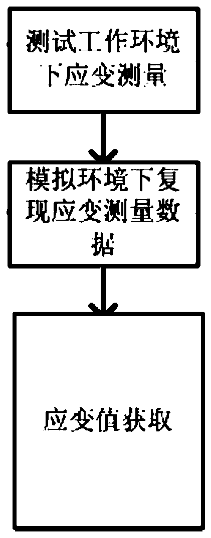
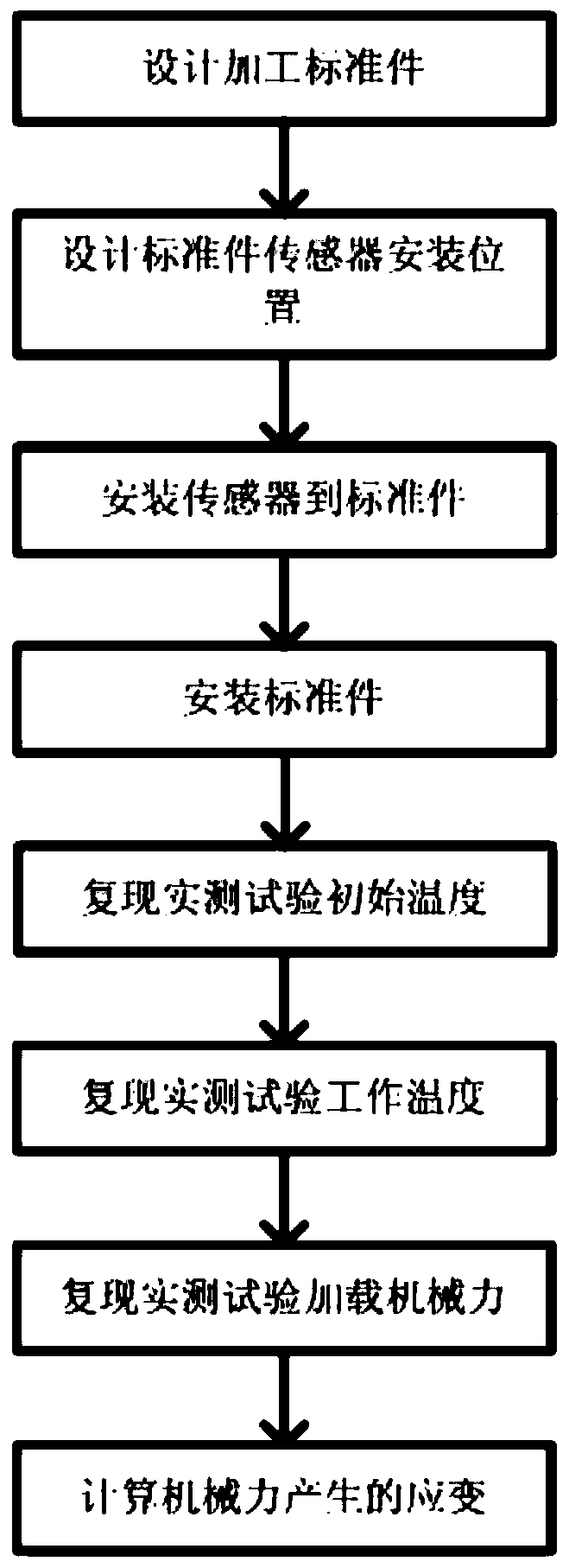
A strain measurement method based on optical fiber sensor in high temperature environment
A fiber optic sensor and strain measurement technology, applied in the field of testing, to achieve the effects of improving accuracy, offsetting hidden error sources, and uniform temperature field distribution
- Summary
- Abstract
- Description
- Claims
- Application Information
AI Technical Summary
Problems solved by technology
Method used
Image
Examples
Embodiment 1
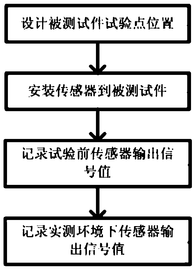
[0043] Step 1. Test the strain measurement in the working environment
[0044] 1) Design the position of the test point of the tested piece: the material of the tested piece is K417G, and design and install the test point at the center of the test piece;
[0045] 2) Install the sensor to the tested piece: Install the fiber grating strain sensor and the fiber grating temperature sensor to the test point using the standard installation process;
[0046] 3) Record the sensor output signal value before the test: connect the fiber grating type strain sensor and the fiber grating type temperature sensor to the demodulation equipment, set the demodulation parameters through the device operating software, ensure that the data acquisition and demodulation are normal, and record the sensor output signal values respectively for X ε0 、X T0 ;
[0047] 4) Record the output signal value of the sensor in the actual measurement environment: install the test piece in the hot wind tunnel te...
Embodiment 2
[0061] Step 1. Test the strain measurement in the working environment
[0062] 1) Design the position of the test point of the tested piece: the material of the tested piece is K417G, and design and install the test point at the center of the test piece;
[0063] 2) Install the sensor to the tested piece: Install the fiber grating strain sensor and the fiber grating temperature sensor to the test point using the standard installation process;
[0064] 3) Record the sensor output signal value before the test: connect the fiber grating type strain sensor and the fiber grating type temperature sensor to the demodulation equipment, set the demodulation parameters through the device operating software, ensure that the data acquisition and demodulation are normal, and record the sensor output signal values respectively for X ε0 、X T0 ;
[0065] 4) Record the output signal value of the sensor in the actual measurement environment: install the test piece in the hot wind tunnel te...
Embodiment 3
[0079] Change the fiber grating type strain sensor and fiber grating type temperature sensor in embodiment 1 to F-P interference type strain sensor and F-P interference type temperature sensor, and other steps are the same as embodiment 1.
PUM
 Abstract
Description
Claims
Application Information
 - R&D
- Intellectual Property
- Life Sciences
- Materials
- Tech Scout
- Unparalleled Data Quality
- Higher Quality Content
- 60% Fewer Hallucinations
Browse by: Latest US Patents, China's latest patents, Technical Efficacy Thesaurus, Application Domain, Technology Topic, Popular Technical Reports.
© 2025 PatSnap. All rights reserved.Legal|Privacy policy|Modern Slavery Act Transparency Statement|Sitemap|About US| Contact US: help@patsnap.com


