A Calibration Method of System Parameters of Double Rotating Compensator Muller Matrix Ellipsometer
A technology of double rotary compensator and rotary compensator, which is applied in the direction of instruments, scientific instruments, complex mathematical operations, etc., can solve the problem that the initial value deviation calibration result cannot be solved, and achieve stable calculation results, good robustness, and avoid system effect of error
- Summary
- Abstract
- Description
- Claims
- Application Information
AI Technical Summary
Problems solved by technology
Method used
Image
Examples
Embodiment 1
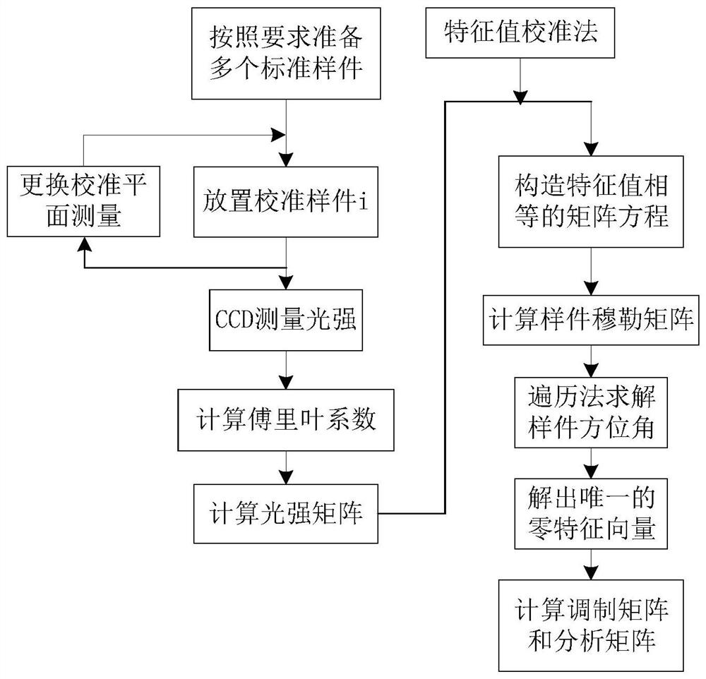
[0037] In an embodiment of the present invention, the calibration sample includes a polarizer with an azimuth angle of 0°, a polarizer with an azimuth angle of about 90°, and a quarter-wave plate with an azimuth angle of about 30°. The test method is as follows: image 3 Shown:
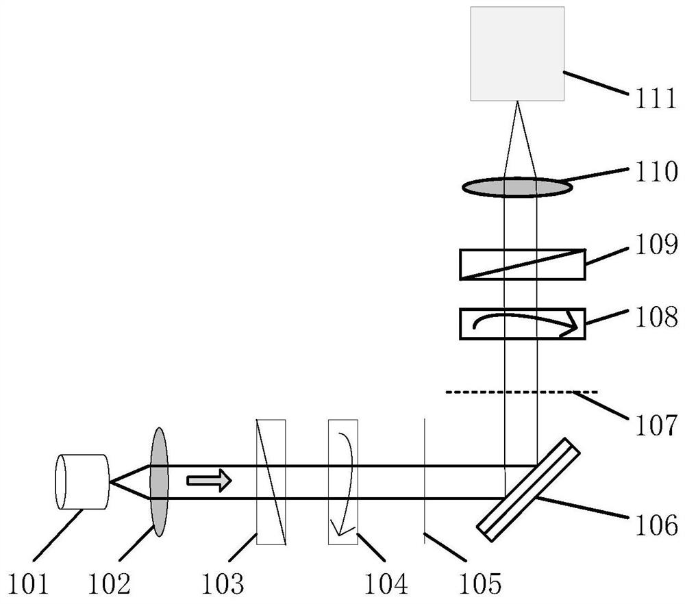
[0038] Step 1, place the above-mentioned three calibration samples on the first calibration plane 105 in turn, align the light path, and complete the data collection of light intensity information, and the result is denoted as I f i (t), where i=1, 2, 3, corresponding to different calibration samples in turn, can collect signals of multiple periods, and then take the average to reduce the influence of random errors in the system on the measurement results.
[0039] Step 2, place the above-mentioned three calibration samples on the second calibration plane 107 in turn, align the light path, and complete the data collection of light intensity information, and the result is denoted as I b i (t), where...
Embodiment 2
[0108] One embodiment of the present invention is aimed at 5:3 double rotation compensator type Muller matrix ellipsometer, implements the specific calibration method process as follows:
[0109] Step 100, according to the formula (7.1) (7.2) (7.3) (7.4) (8) and (9), after obtaining the sampling signal, perform Fourier analysis to obtain the Fourier coefficient, select the corresponding basis vector value and Solve the light intensity matrix D in the form of 5×5.
[0110]
[0111] S W (t)=[1cos10ωt sin10ωt cos20ωt sin20ωt] T (20.2)
[0112] S A (t)=[1cos6ωt sin6ωt cos12ωt sin12ωt] (20.3)
[0113]
[0114] where α i , β j are the Fourier coefficients of the sampled signal.
[0115] Step 200, after obtaining the light intensity matrix corresponding to each group of sampling signals, analyze the eigenvalues of the Mueller matrix of the calibration sample according to the formula (11.1) (11.2), and deduce the calibration sample in the form of the Mueller matrix of ...
PUM
 Abstract
Description
Claims
Application Information
 - R&D
- Intellectual Property
- Life Sciences
- Materials
- Tech Scout
- Unparalleled Data Quality
- Higher Quality Content
- 60% Fewer Hallucinations
Browse by: Latest US Patents, China's latest patents, Technical Efficacy Thesaurus, Application Domain, Technology Topic, Popular Technical Reports.
© 2025 PatSnap. All rights reserved.Legal|Privacy policy|Modern Slavery Act Transparency Statement|Sitemap|About US| Contact US: help@patsnap.com


