Eureka AIR delivers breakthrough ideas for toughest innovation challenges, trusted by R&D personnel around the world.

Different terrain-adaptive solar tracking method

A solar tracking and self-adaptive technology, applied in the direction of using feedback control, etc., can solve the problem of not guaranteeing that photovoltaic modules are not blocked by shadows, and the shadows of front and rear photovoltaic modules can be blocked. The algorithm formula is simple and clear, and the reliability and stability are guaranteed. Effect

Active Publication Date: 2017-07-07
VERSOLSOLAR HANGZHOU
View PDF6 Cites 5 Cited by
  • Summary
  • Abstract
  • Description
  • Claims
  • Application Information

AI Technical Summary

Problems solved by technology

[0005] The general flat single-axis solar tracker adopts the control method of calculating the solar azimuth to control the rotation of the photovoltaic modules according to the astronomical algorithm, but when the tracking system tracks the sun, even if there is a certain distance between the two rows of photovoltaic modules The shadows in the front row cover the photovoltaic modules in the rear and affect the power generation efficiency, but this distance cannot guarantee that the photovoltaic modules will not be blocked by shadows at all times, especially when the sun has just risen or is about to set, and the sun’s altitude angle is very low. Shading is unavoidable if PV modules continue to be aimed at the sun
With the update of the control algorithm, the common flat single-axis tracking system on the market has basically solved the problem of shadow occlusion when the terrain is relatively flat. However, this astronomical algorithm is applied to complex terrain such as the obvious height difference between the front and rear components. In some cases, the front and rear rows of photovoltaic modules still have relatively obvious shadow occlusion

Method used


Image

  • Different terrain-adaptive solar tracking method
  • Different terrain-adaptive solar tracking method
  • Different terrain-adaptive solar tracking method

Examples


Embodiment

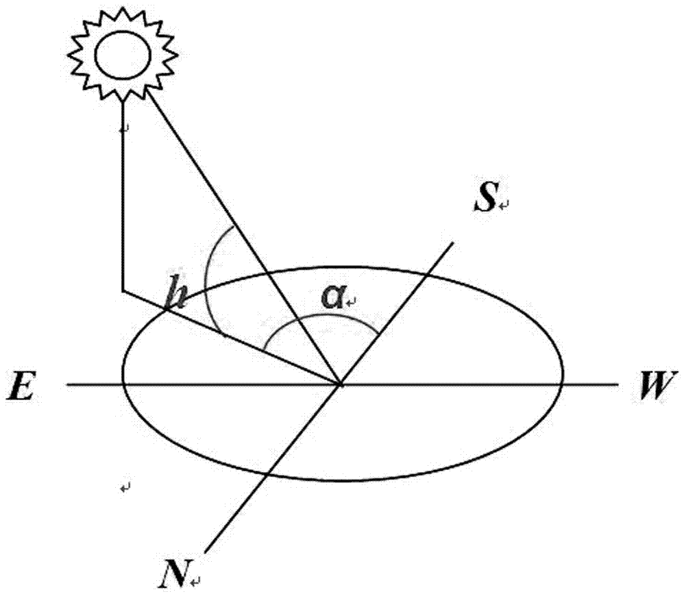
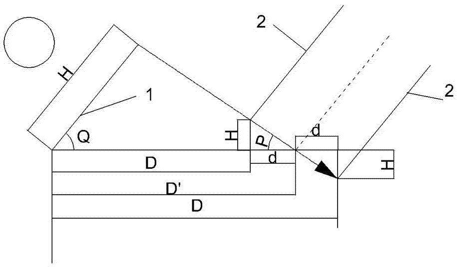
[0034] Such as figure 1 with 2 As shown, different terrain adaptive solar tracking methods, the first step, according to the longitude γ and latitude of the installation place of the solar panel assembly And Beijing time T, calculate the local time t, show the hour angle ω and the declination angle δ of time change; Wherein, t=T-[(120-γ) / 15], ω=(t-12)×15, δ =23.45 sin[360×(284+n) / 365]; second step, calculate the tangent value of P angle according to the tangent value of the sun altitude h and the sine value of the sun azimuth α, tanP=tanh / sin α, P The angle is the angle between a vector perpendicular to the panel and the horizontal plane obtained by projecting the space vector of the sun's rays onto the tracker panel assembly; the calculation formula of the P angle is:

[0035]

[0036]

[0037] tanP = tanh / sinα;

[0038] The third step is to calculate the normal tracking target angle Q of the tracking system according to the tangent value of the P angle obtained in ...


PUM


Abstract

The invention relates to a solar tracking method and particularly relates to a different terrain-adaptive solar tracking method. A solar tracker is provided, and according to the solar tracker, the sun position is accurately calculated based on a modern astronomical algorithm; an equivalent position is designed according to the width of a module, the gap between a front row and a rear row of panel modules and a difference height; and the angle of each panel module is adjusted according to a corresponding calculation formula. According to the different terrain-adaptive solar tracking method, in a condition of not changing the original structure, in the case of terrain complexity and a layout structure with a height difference between the front row and the rear row of photovoltaic modules, no shadows can be ensured to be generated in an east-west direction of the front row and the rear row of photovoltaic modules at any time, maximization of light emission intensity of sun light vertical to the photovoltaic modules is achieved, and the photovoltaic conversion rate is improved. Thus, the technical problem that the solar panel modules are mutually blocked easily to generate shadows in the prior art, receiving of sun light is influenced, and the photovoltaic conversion rate is thus influenced can be solved.

Description

technical field [0001] The invention relates to a solar tracking method, in particular to a different terrain adaptive solar tracking method. Background technique [0002] The development of new energy and renewable clean energy is a common task faced by the whole world. Among new energy sources, photovoltaic power generation has attracted much attention. However, due to the high cost, it has not yet fully entered the market. Photovoltaic power generation market has broad prospects, but the low utilization efficiency of solar energy faces the problems of high construction cost and low return on investment. The installation forms of photovoltaic power generation components mainly include fixed inclination, single-axis tracking, and dual-axis tracking. [0003] The fixed-inclination installation means that the components are fixed on the ground at a certain inclination, and the components are static during the entire power generation process. This installation method is sim...

Claims


Application Information

Patent Timeline
IPC IPC(8): G05D3/12
CPCG05D3/12
Inventor 包西平吴克明孙伟胡湘江
Owner VERSOLSOLAR HANGZHOU
Why Eureka
Eureka Blog
Learn More