
Tremor stability domain lobe graph modeling method based on ball-end milling cutter and workpiece contact area

A ball-end milling cutter and contact area technology, which is applied in special data processing applications, instruments, electrical digital data processing, etc., can solve the problem of inability to accurately determine the number of teeth involved in cutting, the actual cutting position, and reduce the accuracy of lobe diagrams , Affecting the scope of application of leaflet diagrams and other issues

Active Publication Date: 2017-07-07
DALIAN UNIV OF TECH
View PDF1 Cites 14 Cited by
  • Summary
  • Abstract
  • Description
  • Claims
  • Application Information

AI Technical Summary

Problems solved by technology

However, the current flutter stability domain lobe diagram modeling methods such as the ZOA method and the time domain method developed on the basis of it are mainly aimed at cylindrical milling cutters, and there are few methods for spherical milling cutters. During the modeling process, it is impossible to accurately determine the number of teeth involved in cutting instantaneously and the actual cutting position of the teeth involved in cutting. Instead, the lobe map can only be constructed by taking the workpiece processed by the plane of the three-axis CNC machine tool as the object. At the same time, the The helix angle of the cutting edge of the milling cutter is simplified as zero degrees, which seriously affects the scope of application of the lobe map and reduces the accuracy of the lobe map

Method used


Image

  • Tremor stability domain lobe graph modeling method based on ball-end milling cutter and workpiece contact area
  • Tremor stability domain lobe graph modeling method based on ball-end milling cutter and workpiece contact area
  • Tremor stability domain lobe graph modeling method based on ball-end milling cutter and workpiece contact area

Examples


Embodiment Construction

[0106] The specific embodiments of the present invention will be described in detail below in conjunction with the technical solutions and accompanying drawings.

[0107] A method for constructing a lobe map of a chatter stable domain during machining of a ball end milling cutter, comprising the following steps:

[0108] Step 1, establish ball end milling cutter tool-workpiece dynamics equation

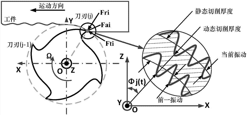
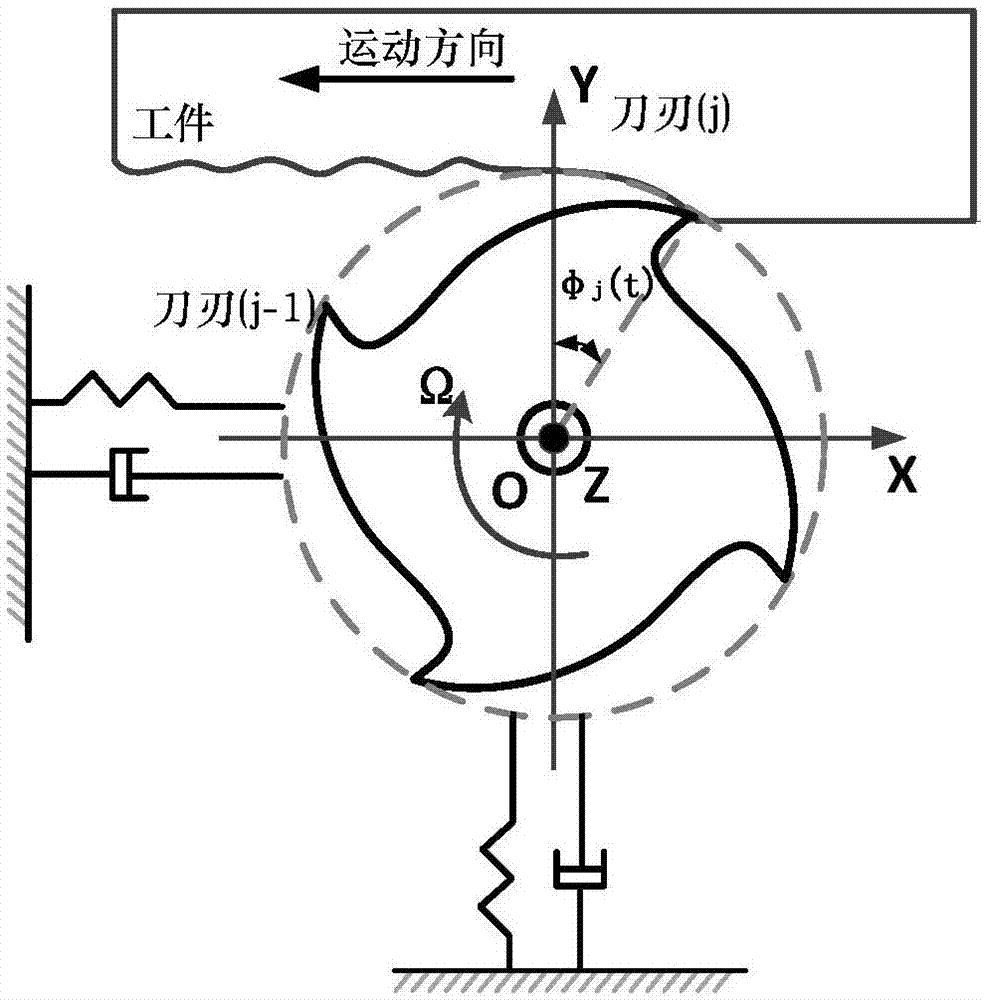
[0109] Such as image 3 As shown, the ball milling cutter tool-workpiece system is simplified to a two-degree-of-freedom system, and only the tool vibration factors in the feed direction x and normal y directions are considered, and the following dynamic equations are established:

[0110]

[0111] Among them, m tx is the modal mass of the tool system in the x direction, m ty is the modal mass of the tool system in the x direction; ξ x is the damping coefficient of the tool system in the x direction, ξ y is the damping coefficient of the tool system in the y direction; ω nx T...


PUM


Abstract

The invention discloses a tremor stability domain lobe graph modeling method based on a ball-end milling cutter and workpiece contact area. The all discrete time domain solving method of a milling system two-order kinetic equation is taken as a principal line; on the basis that an arc cutting and lag period is equal to a single-tooth cutting period in the single-tooth cutting period of the ball-end milling cutter, through the projection boundary equation of the ball-end milling cutter and workpiece contact area and the projection equation of different moments, the amount of blades which participate in cutting and the practical cutting position of the blade which participate in the cutting blade in one lag period can be extracted; and a tremor stability domain lobe graph in the ball-end milling cutter cutting process is constructed. The method is not limited to plane machining on a three-axis machine tool, the contact area of the ball-end milling cutter and the workpiece on a certain cutter location point can be obtained, and the method can be applied to construct the lobe graph of the cutter location point.

Description

technical field [0001] The invention belongs to the field of advanced manufacturing technology, and relates to a modeling method of a chatter stable domain during milling and cutting, in particular a modeling method of a lobe diagram of a chatter stable domain during the cutting process of a ball end milling cutter on a numerically controlled machine tool. Background technique [0002] The manufacturing industry as the pillar of national economic growth is a traditional field. It has been developed for hundreds of years. It has established a relatively systematic theoretical system and accumulated rich practical experience. However, with the improvement of science and technology, the machinery manufacturing industry is facing New challenges force the development of mechanical manufacturing technology towards high speed, high efficiency and high precision. [0003] High-speed milling is one of the most important basic technologies in advanced manufacturing technology. It is t...

Claims


Application Information

Patent Timeline
IPC IPC(8): G06F17/50
CPCG06F30/17G06F30/20
Inventor 李宏坤代月帮魏兆成
Owner DALIAN UNIV OF TECH
Learn More