A cooling and heating integrated box structure

A box structure, hot and cold technology, applied in structural parts, electrochemical generators, batteries, etc., can solve the problems of increased costs, high process and assembly requirements, and high assembly requirements for liquid cooling systems and heating systems, and saves purchases. Cost, design flexibility, compact structure

Active Publication Date: 2020-02-14
TIANJIN ENERGIES
View PDF6 Cites 1 Cited by
  • Summary
  • Abstract
  • Description
  • Claims
  • Application Information

AI Technical Summary

Problems solved by technology

[0003] At present, the battery pack liquid cooling system mainly fixes cooling devices such as cold plates inside the box through bolting, riveting, welding, bonding, etc., which requires high technology and assembly, low efficiency in mass production, and structural strength Low, and there will be a risk of liquid leakage; the heating system is traditionally designed with a heater, which requires high assembly requirements and occupies a certain amount of space
Liquid cooling and heating systems add cost, require more space and mass

Method used


Image

  • A cooling and heating integrated box structure
  • A cooling and heating integrated box structure
  • A cooling and heating integrated box structure

Examples


Embodiment 1

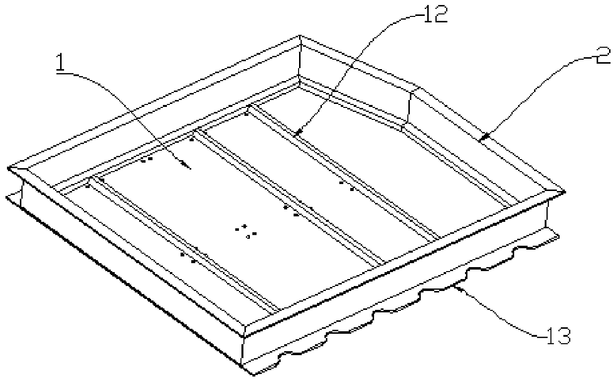
[0053] Such as Figure 1-7 As shown, the integrated cooling and heating box structure of this embodiment is a single-layer structure, specifically, as figure 1 As shown, the box structure includes a box body with an upper opening. The box body includes a bottom plate 1 and a side plate 2. The bottom plate 1 and the side plates 2 enclose a storage cavity for accommodating batteries. Inside the bottom plate 1 are alternately arranged liquid Cooling system and heating system.

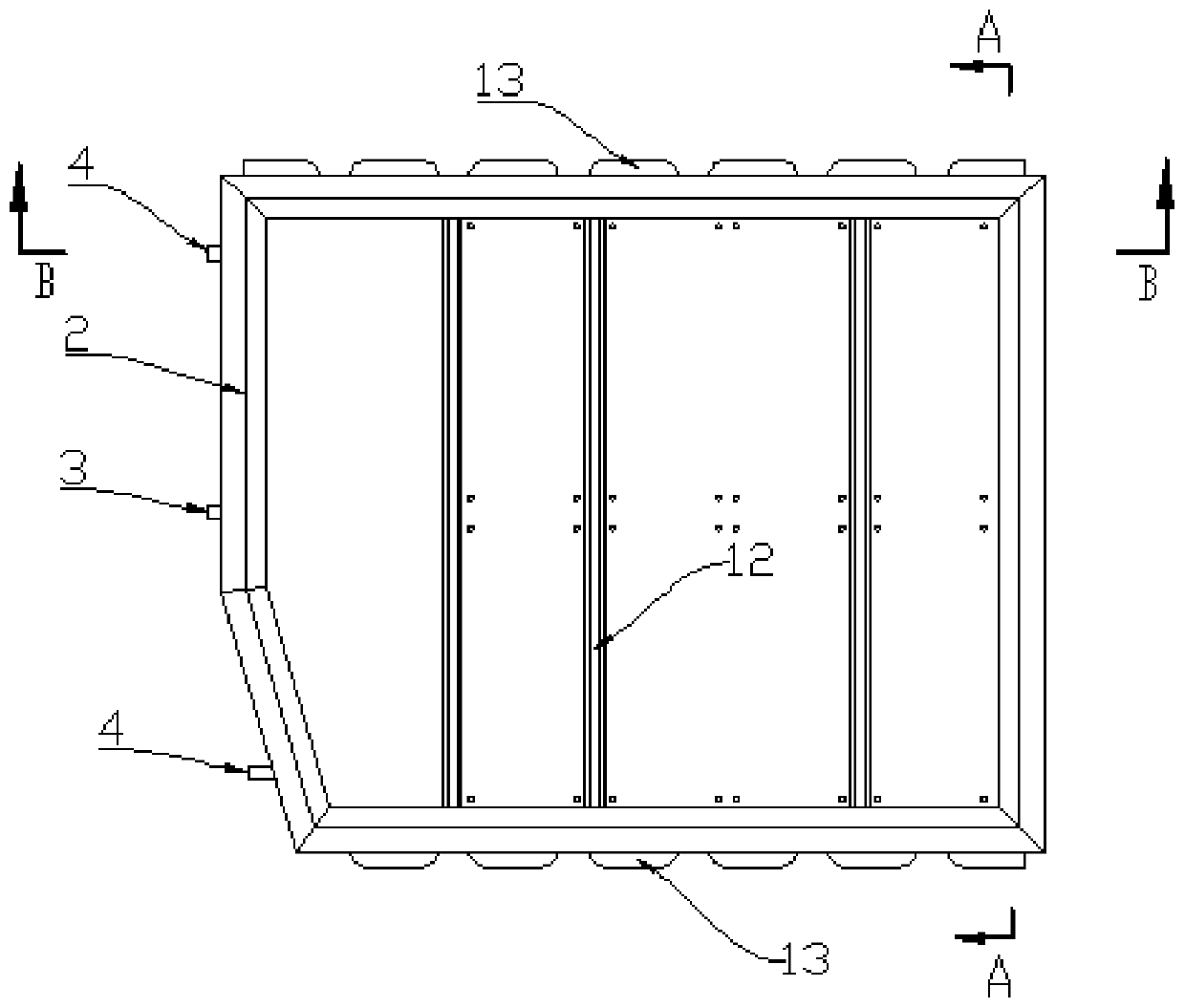
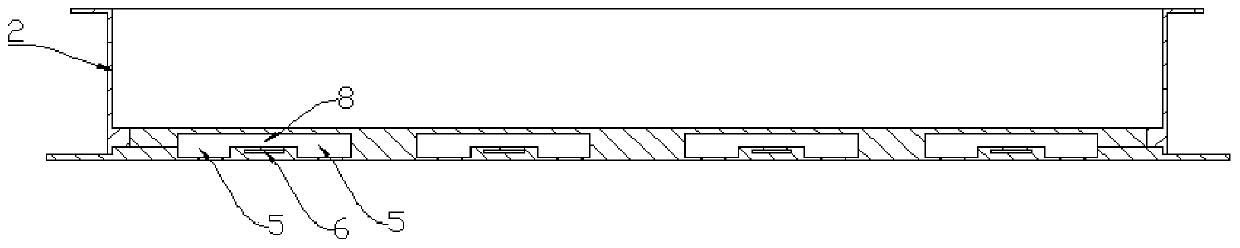
[0054] Such as figure 2 , Figure 4 with Figure 5 As shown, the side plate 2 is provided with a fluid inlet 3 and two fluid outlets 4 (one in and two out), which communicate with the liquid cooling system. The fluid inlet 3 is arranged in the middle of one side plate 2, and the two fluid outlets 4 It is symmetrically arranged at both ends of the side plate 2 . Such as Image 6 As shown, the liquid cooling system is a coolant flow channel 5 distributed in a serpentine shape inside the bottom plate 1...

Embodiment 2

[0062] The integrated cooling and heating box structure of this embodiment is a double-layer structure (such as Figure 12 with Figure 13 shown), specifically, as Figure 8 As shown, the box structure includes a box body with an upper opening. The box body includes a bottom plate 1 and a side plate 2. The bottom plate 1 and the side plates 2 enclose a storage cavity for accommodating batteries. Inside the bottom plate 1 are alternately arranged liquid Cooling system and heating system.

[0063] Such as Figure 14 with Figure 15 As shown, the side plate 2 is provided with a fluid inlet 3 and two fluid outlets 4 (one in and two out), which communicate with the liquid cooling system. The fluid inlet 3 is arranged in the middle of one side plate 2, and the two fluid outlets 4 It is symmetrically arranged at both ends of the side plate 2 . Such as Image 6 As shown, the liquid cooling system is a coolant flow channel 5 distributed in a serpentine shape inside the bottom pla...


PUM


Abstract

The invention provides a cooling and heating integrated box structure, which includes a box main body with an upper opening, the box main body includes a bottom plate and side plates, the bottom plate and side plates enclose an accommodating cavity for accommodating batteries, and the inside of the bottom plate is alternately arranged There is a liquid cooling system and a heating system. At least one fluid inlet and at least one fluid outlet connected to the liquid cooling system are arranged in the side plate. The liquid cooling system is a cooling liquid flow channel distributed in a serpentine shape inside the bottom plate. The first cavity between adjacent cooling liquid flow channels and the heating device filled in the first cavity, and a flow channel bridge for changing the flow direction of the fluid is provided at the reversing position of the cooling liquid flow channel. The box structure of the present invention highly integrates the liquid cooling system, the heating system, the thermal insulation system and the profile box, which improves the battery weight energy density ratio and volume energy density ratio, and reduces or even eliminates the risk of coolant leakage.

Description

technical field [0001] The invention belongs to the field of battery boxes, and in particular relates to a cooling and heating integrated box structure. Background technique [0002] With the rapid development of the new energy vehicle market, the demand for innovation in thermal management technology, integration, and integrated technology is becoming more and more intense. With the increase in energy, the heat generated by the battery is also increasing. And natural cooling can no longer meet the requirements of heat dissipation. In the event of an accident, if the heat cannot be exported in time, it will easily cause the thermal runaway of the battery; and because the antifreeze has a high specific heat capacity, it can take away a large amount of heat per unit time. The cold solution can better meet the heat dissipation requirements of the battery module. In addition, when the battery is at low temperature, the battery system is generally heated by the PTC before chargin...

Claims


Application Information

Patent Timeline
Patent Type & Authority Patents(China)
IPC IPC(8): H01M2/10H01M10/613H01M10/615H01M10/625H01M10/6556H01M10/6571H01M10/6572H01M10/658H01M10/6568H01M50/249
CPCH01M10/613H01M10/615H01M10/625H01M10/6556H01M10/6568H01M10/6571H01M10/6572H01M10/658H01M2220/20H01M50/20Y02E60/10
Inventor 伊炳希从长杰陈保国彭月猛豆卫广赵博文于江梁宏伟王驰伟
Owner TIANJIN ENERGIES
Why Eureka
Try Eureka