
Gas humidifying equipment

A humidification equipment, gas technology, applied in the direction of electrical components, climate sustainability, sustainable manufacturing/processing, etc., can solve the problems of bulky, large bubble size, poor aging resistance, etc., to achieve the benefit of heat transfer and transfer Quality, humidification performance improvement, easy disassembly and maintenance

Pending Publication Date: 2017-07-07
上海泛町智能科技有限公司
View PDF3 Cites 23 Cited by
  • Summary
  • Abstract
  • Description
  • Claims
  • Application Information

AI Technical Summary

Problems solved by technology

Humidifiers with bubbling humidification have a simple structure and cheap materials; however, due to their low humidification efficiency, they require relatively large water tanks, which are bulky and have poor humidification effects
[0004] The Chinese patent application with the publication number CN 102332591 discloses a reaction gas humidifier for fuel cells. The humidifier is based on the principle of bubbling humidification, but there is no bubbler, so the bubbles are large and the humidification efficiency is low, so the general It is only suitable for low-power fuel cell laboratory tests, but it cannot meet the requirements for high-power (above 10kW) fuel cells
The Chinese patent application with publication number CN 203774400 proposed a high-efficiency fuel cell humidifier for mobile applications. Efficiency, but there are still some technical defects, such as large bubble size after bubbling, insufficient rigidity of the bubbler, poor aging resistance, unstable humidification performance, etc.
The Chinese patent application with the publication number CN101577338 discloses a fuel cell humidifier, which proposes a method of combining atomization and heat exchangers to improve the humidification efficiency, but the additional heat exchanger structure increases the complexity of the structure, and For a large flow of airflow, the heat exchange effect is not very good, resulting in unstable humidification (there is condensed water in the gas or insufficient humidification)

Method used


Image

  • Gas humidifying equipment
  • Gas humidifying equipment

Examples


Embodiment Construction

[0022] The present invention will be further described below in conjunction with the embodiments shown in the accompanying drawings.

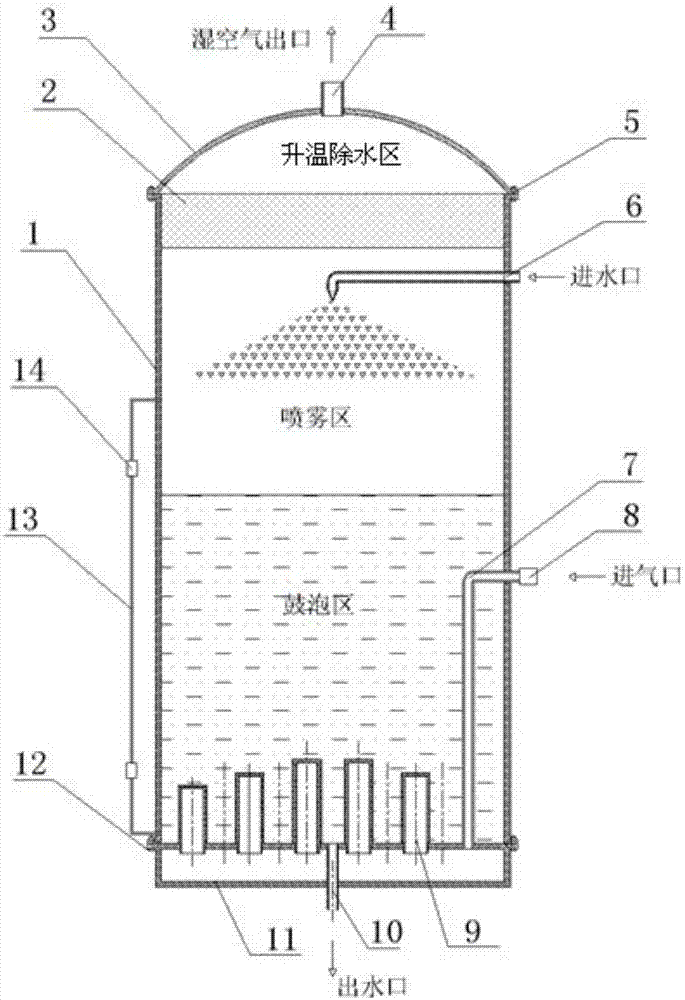
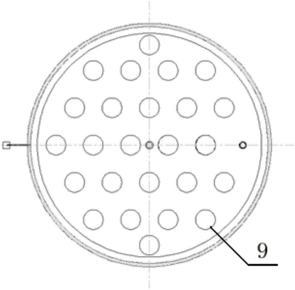
[0023] The present invention proposes a gas humidification device, especially a gas humidification device for a fuel cell, which includes a liquid storage device, a bubbling part, a spray part, and a temperature-rising and water-removing part arranged in sequence from bottom to top to separate the gas. Layer humidification. Wherein, the bubbling part includes a bubbling device and a wetting liquid, and the wetting liquid is contained in a liquid storage device, so that the gas is sent into the wetting liquid by the bubbling device; The gas is sprayed and humidified; the heating and dewatering part includes a heating and dewatering device to heat and dewater the gas that has been sprayed and humidified. On the one hand, the purpose of dewatering can be achieved by increasing the temperature, and on the other hand, it can also prevent air from be...


PUM


Abstract

The invention provides gas humidifying equipment and belongs to the technical field of humidification. The equipment comprises a liquid storage device, and a bubbling portion, a spraying portion and a temperature-raising and water-removing portion which are successively arranged from bottom to top for humidifying gas in a layered manner, wherein the bubbling portion comprises a bubbling device and a humidifying liquid, the humidifying liquid is held in the liquid storage device, and gas is fed into the humidifying liquid through the bubbling device; the spraying portion comprises a spraying device so as to spray and humidify gas diffused from the humidifying liquid; and the temperature-raising and water-removing portion comprises a temperature-raising and water-removing device for raising the temperature and removing water for the sprayed and humidified gas. By adopting a method of humidification in a layered manner, the humidifying efficiency is greatly increased on a basis of simplifying the structure and reducing the cost, the humidifying performance is optimized, and the equipment is quite suitable for a humidifying demand on a high-power fuel cell.

Description

technical field [0001] The invention belongs to the technical field of humidification, and relates to a humidification device, in particular to a gas humidification device. Background technique [0002] A fuel cell is an electrochemical reaction device that directly converts chemical energy into electrical energy. There are various types of fuel cells depending on the electrolyte. Among them, the proton exchange membrane fuel cell has low operating temperature, high current density, fast response speed, and stable performance; and the reaction product is only water, which is not corrosive. Therefore, the proton exchange membrane fuel cell can be widely used in the field of mobile power. Proton exchange membrane fuel cells use hydrogen and oxygen to generate electricity. When hydrogen and oxygen are supplied to the anode and cathode of the fuel cell respectively, the reaction gas diffuses through the diffusion layer, and the hydrogen atoms entering the porous anode are ads...

Claims


Application Information

Patent Timeline
IPC IPC(8): H01M8/04119
CPCH01M8/04126Y02E60/50Y02P70/50
Inventor 袁昆徐博吴伟袁静婕
Owner 上海泛町智能科技有限公司
Learn More