Low-voltage-and-current self-matching grid switch charge pump

A gate switch, low-voltage technology, applied in the field of low-voltage current self-matching gate switch charge pump, can solve the problem of being in the linear region of the output current source, it is difficult for the charge and discharge currents to be equal to each other, and the charge and discharge current cannot be kept constant, etc. problem, to achieve constant charge and discharge current and increase output impedance

Active Publication Date: 2017-07-07
SOUTHEAST UNIV
View PDF4 Cites 5 Cited by
  • Summary
  • Abstract
  • Description
  • Claims
  • Application Information

AI Technical Summary

Problems solved by technology

[0003] The technical problem to be solved by the present invention is to overcome the deficiencies of the prior art, provide a low-voltage current self-matching gate switch charge pump, and solve the problem that the output voltage of the charge pump is often in the output current source under the low voltage condition of the existing charge pump. In the linear region, the charge and discharge currents cannot be kept constant, and it is difficult to ensure that the charge and discharge currents are equal to each other. The charge pump uses a low-voltage amplifier to form a feedback loop to track the voltage change of the output node and adjust the gate of the charge and discharge current source in real time. Pole voltage, so that the charging and discharging current of the charge pump is always equal to the reference current

Method used


Image

  • Low-voltage-and-current self-matching grid switch charge pump
  • Low-voltage-and-current self-matching grid switch charge pump

Examples


Embodiment Construction

[0015] Embodiments of the present invention will be described below in conjunction with the accompanying drawings.

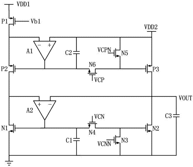
[0016] Such as figure 1 As shown, the present invention provides a low-voltage current self-matching gate switch charge pump, the charge pump includes a charging circuit and a discharging circuit, wherein the charging circuit is composed of a first power supply VDD1, a second power supply VDD2, a first error amplifier, Composed of first to third PMOS transistors and a pair of NMOS transistors, the charging circuit is used to clamp the drain of the reference current to the second power supply through negative feedback after being connected to the first power supply, so that the charging PMOS transistor P3 and the reference branch The voltages of each port of the series transistor P2 in the circuit are equal, that is, when the output voltage changes, the current flowing through the second PMOS transistor is kept equal to the input reference current, and the gate-s...


PUM


Abstract

The invention discloses a low-voltage-and-current self-matching grid switch charge pump comprising a charging circuit and a discharging circuit. The charging circuit consists of a first power supply, a second power source, a first error amplifier, a first PMOS tube, a second PMOS tube, a third PMOS tube, and a pair of NMOS tubes and is capable of clamping a drain electrode of an input reference current source to the second power source by negative feedback, so that voltages of all ports of the third PMOS tube in a charging loop and the second PMOS tube connected in series in a reference branch are equal and thus the charging current can be equal to the input reference current when the output voltage changes. The discharging circuit is a feedback loop formed by a low-voltage rail-to-rail error amplifier and four NMOS tubes and is used for tracking a voltage change of an output node and adjusting grid voltages of the NMOS tubes in the discharging circuit in real time, so that the discharging current is equal to the input reference current all the time under different output voltages. Therefore, the charging and discharging currents are equal under different output voltages; and the output impedance of the input reference current source is improved and thus the current source becomes constant.

Description

technical field [0001] The invention relates to a low-voltage current self-matching gate switch charge pump, which belongs to the technical field of charge pumps. Background technique [0002] With the continuous reduction of process size and the demand for low power consumption, the power supply voltage of radio frequency and analog integrated circuits is constantly evolving towards a lower direction. Designers began to try to make RF transceiver circuits work at 0.7V or lower supply voltage. However, due to the constraints of the leakage current problem, the threshold voltage of the transistor has not continued to decrease with the feature size but is stable at the level of 350mV~450mV, which brings great challenges to traditional circuit design. In the design of the frequency synthesizer, the reduction of the power supply voltage has the most serious impact on the charge pump. Limited by the voltage margin and the output impedance of the charge and discharge current sou...

Claims


Application Information

Patent Timeline
Patent Type & Authority Applications(China)
IPC IPC(8): H02M3/07
CPCH02M3/073H02M3/078
Inventor 陈超
Owner SOUTHEAST UNIV
Why Eureka
Try Eureka