Glass substrate air flotation device with deformation detection function and detection method

A glass substrate and deformation technology, applied in the detection field, can solve the problems of unable to monitor the deformation of the glass substrate in real time, reduce the accuracy of defect detection, and increase the cost, etc., meet high hardware configuration requirements, reduce uneven pressure distribution of the gas film, and uniform gas film The effect of pressure

Active Publication Date: 2017-07-11
JIANGSU UNIV OF SCI & TECH
View PDF12 Cites 13 Cited by
  • Summary
  • Abstract
  • Description
  • Claims
  • Application Information

AI Technical Summary

Problems solved by technology

[0006] Although the above-mentioned technical solutions can realize non-contact transportation of large glass substrates, none of them can realize real-time monitoring of glass substrate deformation.
In the glass substrate production line, if the glass quality needs to be inspected by machine vision, the deformation of the glass substrate caused by the pressure of the air film must be strictly controlled, otherwise, the bending deformation of the glass substrate will reduce the detection accuracy of defects
Usually, an external laser displacement sensor can detect the deformation of the glass substrate. However, the efficiency of large-scale detection is low and it is prone to large errors.
Increasing the number of laser displacement sensors can improve the efficiency of glass substrate deformation detection, but it also leads to a substantial increase in cost

Method used


Image

  • Glass substrate air flotation device with deformation detection function and detection method
  • Glass substrate air flotation device with deformation detection function and detection method
  • Glass substrate air flotation device with deformation detection function and detection method

Examples


Embodiment Construction

[0045] The present invention will be further described below in conjunction with the accompanying drawings.

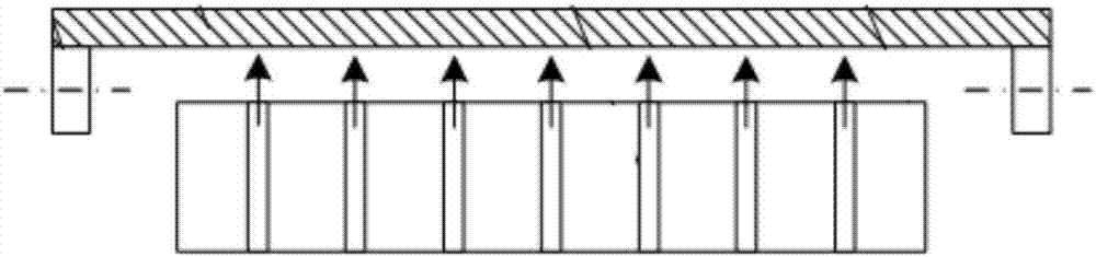
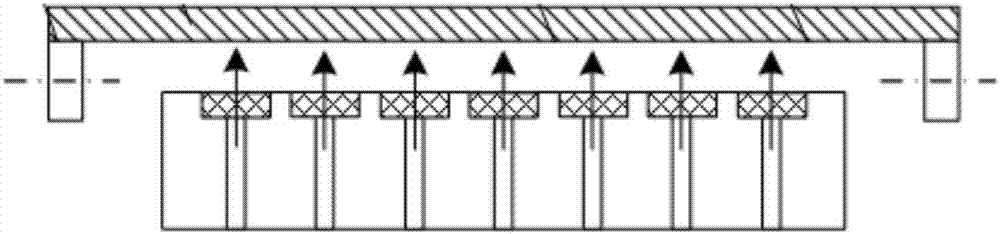
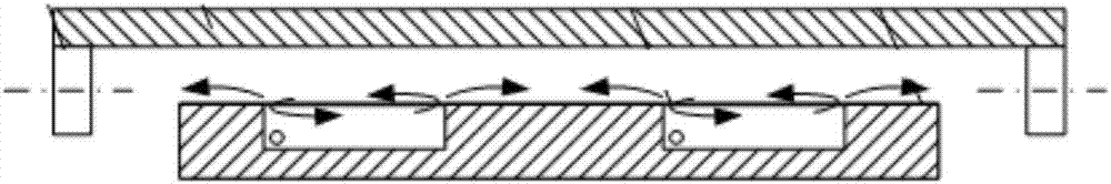
[0046] Such as Figure 1 to Figure 9 As shown, the glass substrate air flotation device with deformation detection function of the present invention includes a transport platform 1, a fixed platform 5 and a base 9, the transport platform 1 is connected to the fixed platform 5 through a leveling nut 4, and the fixed platform 5 passes through The support column 10 is connected with the base 9, and the two sides of the transportation platform 1 are provided with a driving device for driving the movement of the glass substrate 2. The driving device is a driving roller 3. The transportation platform 1 is provided with several uniformly arranged transportation air holes. The platform 1 is provided with criss-cross pressure equalizing grooves, which divide the transportation platform 1 into several squares, and the conveying air holes are located in the squares, and there are...


PUM

PropertyMeasurementUnit
diameteraaaaaaaaaa
depthaaaaaaaaaa

Abstract

The invention discloses a glass substrate air flotation device with a deformation detection function. The glass substrate air flotation device comprises a transporting platform, a fixed platform and a base. The fixed platform is connected with the base through supporting columns. Driving devices used for driving a glass substrate to move are arranged on the two sides of the transporting platform. The transporting platform is provided with a plurality of conveying air holes arranged evenly. A sintered metal porous material is embedded in the top end of each conveying air hole. The bottom of each conveying air hole is connected with an air conveying pipe. The air conveying pipes are connected with a pressure reduction valve through a flowmeter. The pressure reduction valve is connected with an air source through a hose. At least two small holes are formed in the periphery of each conveying air hole of the transporting platform, the bottom of each small hole is connected with a pressure sensor through an air pipe, and the pressure sensors and the signal output end of the flowmeter are connected with an input conversion module. The glass substrate air flotation device with the deformation detection function has the advantages of being clean, free of pollution, heating and magnetism generation and the like, and a pneumatic system is easy to maintain and simple in structure.

Description

technical field [0001] The invention relates to a glass substrate air flotation device with a deformation detection function and a detection method, belonging to the detection field. Background technique [0002] The traditional liquid crystal glass substrate handling adopts the contact transportation method, that is, the workpiece is in direct contact with the surface of the transportation device (such as roller drive, vacuum chuck, etc.), which is likely to cause scratches and cracks on the surface of the glass substrate, and there is also static electricity. Many problems such as metal pollution and metal pollution have seriously affected product quality and have been unable to meet the needs of current technological development. On the other hand, due to the constraints of friction, it is difficult to increase the transport speed in this contact transport mode, which also limits the further improvement of production efficiency. At present, the glass substrate is develop...

Claims


Application Information

Patent Timeline
Patent Type & Authority Applications(China)
IPC IPC(8): B65G49/06B65G51/03G01L11/00
CPCG01L11/00B65G49/063B65G51/035
Inventor 钟伟顾小玉
Owner JIANGSU UNIV OF SCI & TECH
Why Eureka
Try Eureka