
Shoulder joint subluxation shoulder protecting device

A technology for subluxation and shoulder joints, applied in the medical field, can solve problems such as edema of the upper limbs on the hemiplegic side, unsatisfactory use effect, and influence on venous return, etc., and achieve the effect of large market value, simple structure, smooth interface and no friction

Active Publication Date: 2017-07-14
PEKING UNIV THIRD HOSPITAL
View PDF8 Cites 4 Cited by
  • Summary
  • Abstract
  • Description
  • Claims
  • Application Information

AI Technical Summary

Problems solved by technology

Currently commonly used shoulder pads, see Image 6 , the use effect is not very ideal. This method of lifting the weight of the upper body through the lower cuff is largely affected by the tightness of the cuff binding. Only when it is tied tightly can the weight of the upper body be effectively fixed on the upper shoulder belt. , reduce the incidence of subluxation
However, if the cuff is too tight, it will cause discomfort to the patient, and the upper limb on the hemiplegic side is prone to edema, and a tight cuff will affect the venous return and aggravate the swelling.
Therefore we often see the patient's shoulder pads loosely hung on the shoulders, application number: CN201120010942. It is a reduction belt for hemiplegic shoulder joint subluxation. These two technical solutions cannot achieve a good fixation effect on the joint and will still cause edema. Therefore, a shoulder support device for shoulder joint subluxation is proposed

Method used


Image

  • Shoulder joint subluxation shoulder protecting device
  • Shoulder joint subluxation shoulder protecting device
  • Shoulder joint subluxation shoulder protecting device

Examples


Embodiment Construction

[0023] The following will clearly and completely describe the technical solutions in the embodiments of the present invention with reference to the accompanying drawings in the embodiments of the present invention. Obviously, the described embodiments are only some, not all, embodiments of the present invention. Based on the embodiments of the present invention, all other embodiments obtained by persons of ordinary skill in the art without making creative efforts belong to the protection scope of the present invention.

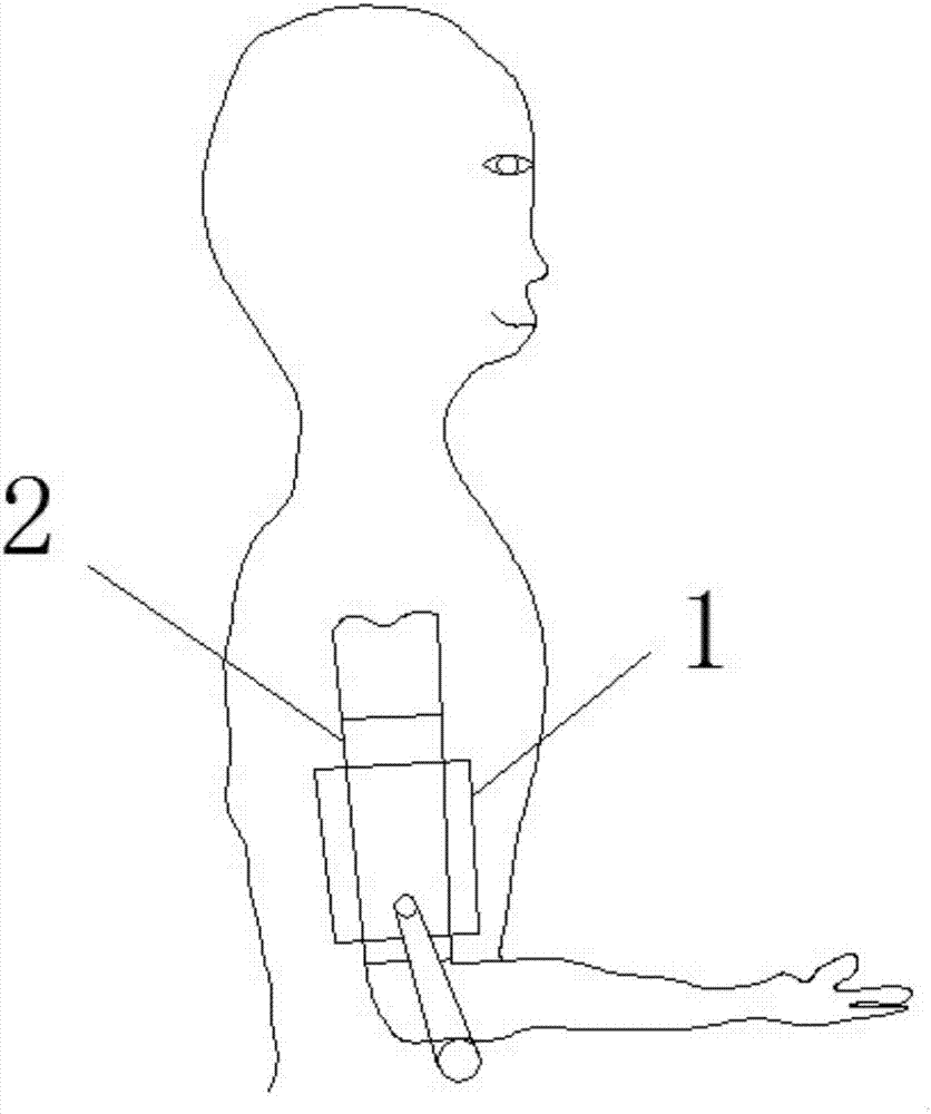
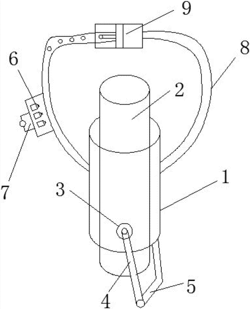
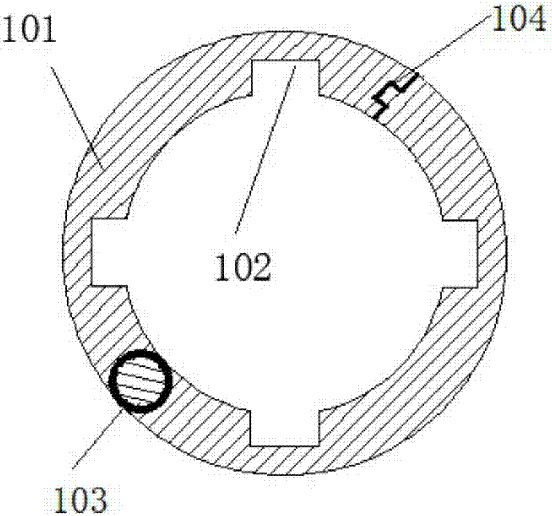
[0024] see Figure 1-6 , the present invention provides a technical solution:

[0025] A shoulder protection device for shoulder joint subluxation, comprising an outer tube 1 and an inner tube 2, the outer tube 1 and the inner tube 2 are made of thermoplastic materials, the inner tube 2 is movably inserted into the outer tube 1, and The lower side wall of the outer tube 1 is rotationally connected to one end of the steel frame 4 through the connecting part 3,...


PUM


Abstract

The invention discloses a shoulder joint subluxation shoulder protecting device, which comprises an outer layer tube and an inner layer tube. The shoulder joint subluxation shoulder protecting device is characterized in that the inner layer tube is movably inserted and connected in the outer layer tube; the side wall of the lower end of the outer layer tube is rotationally connected with one end of a steel frame through a connecting part; the other end of the steel frame is connected with the rotating shaft; the upper end of the outer layer tube is connected with a hanging belt. The shoulder joint subluxation shoulder protecting device has the advantages that the structure is simple; a conventional hanging method is not used; the lever effect is used; through the gravity of the self front arm of a patient, the upper arm is lifted up. The double-side-sleeve structure is designed; the inner and outer layer tubes are tightly attached and sleeved; the interface is smooth and does not have friction; the sliding is smooth; a strip-shaped clamp groove and a strip-shaped clamp block are arranged between the inner and outer layers and are mutually clamped and connected; the relative rotation is avoided. During the wearing, the inner layer tube is opened, is buckled on the upper arm, and penetrates into the outer layer sleeve; a shoulder device is worn through elbow bending; the height of the outer layer sleeve is regulated, so that the lower rotating shaft just powerfully supports the forearm.

Description

technical field [0001] The invention relates to the field of medical technology, in particular to a shoulder protection device for shoulder joint subluxation. Background technique [0002] The hemiplegic side of stroke patients is prone to shoulder subluxation. The reason is that the deltoid muscle, rotator cuff and other muscle groups are paralyzed, and the humeral head moves downward due to the gravity of the upper limb. Currently commonly used shoulder pads, see Image 6 , the use effect is not very ideal. This method of lifting the weight of the upper body through the lower cuff is largely affected by the tightness of the cuff binding. Only when it is tied tightly can the weight of the upper body be effectively fixed on the upper shoulder belt. On, reduce the occurrence of subluxation. However, if the cuff is too tight, it will cause discomfort to the patient, and the upper limb on the hemiplegic side is prone to edema, and a tight cuff will affect the venous return and...

Claims


Application Information

Patent Timeline
IPC IPC(8): A61F5/05
CPCA61F5/0102A61F5/05A61F5/013A61F2005/0181
Inventor 谷莉周谋望刘楠
Owner PEKING UNIV THIRD HOSPITAL
Learn More