Construction method of anti-seepage wall of hydropower station

A construction method and technology for hydropower stations, applied in excavation, sheet pile walls, foundation structure engineering, etc., can solve problems such as serious water seepage, hidden safety hazards, and reduced safety of slot holes, and achieve simple construction technology, obvious economic benefits, and convenient quality The effect of control

Active Publication Date: 2017-07-14
POWERCHINA XIBEI ENG
View PDF5 Cites 17 Cited by
  • Summary
  • Abstract
  • Description
  • Claims
  • Application Information

AI Technical Summary

Problems solved by technology

[0003] 1. The altitude of the construction work surface of some hydropower station anti-seepage walls is about 3069m, which belongs to high-altitude areas, and the construction efficiency of construction machinery and construction personnel will be reduced
[0004] 2. In these plateau areas, the soil layer of landslide accumulation blocks of crushed stones, sand pebbles and gravels contains boulders and boulders; the closure dragon mouth is 33.3m wide, and there are many large boulders and boulders thrown and filled at the dragon mouth during closure, which will restrict the anti-seepage wall. Rapid groove construction, while the safety of the groove is reduced, forming a safety hazard
[0005] 3. During the construction of the hydropower station, the upstream cofferdam was backfilled with sand and gravel, which caused serious water seepage, especially in the Longkou section, where the air-tight effect was not good, and there were large seepage channels, which increased the difficulty of forming trenches and endangered the safety of equipment and weirs

Method used


Image

  • Construction method of anti-seepage wall of hydropower station
  • Construction method of anti-seepage wall of hydropower station
  • Construction method of anti-seepage wall of hydropower station

Examples


Embodiment 1

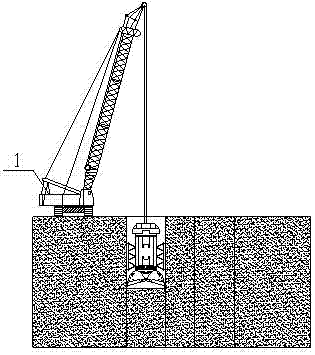
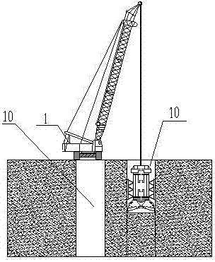
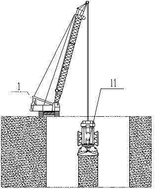
[0035] Such as Figure 1 to Figure 14 As shown, the present invention provides a construction method for the anti-seepage wall of a hydropower station. The anti-seepage wall is arranged on the wall foundation in the hydropower station, and the wall foundation is a soft foundation, cofferdam or dam in the hydropower station. It is characterized in that: the method includes The first-phase groove section construction and the second-phase groove section construction carried out successively on the wall foundation; the first-phase groove section and the second-phase groove section are staggered; the first-phase groove section construction specifically includes the following steps: Step 1 , use grab bucket 1 to grab the first-stage main hole 10 on one side of the wall foundation; step 2, use grab bucket 1 to grab the other side first-stage main hole 10 on the wall foundation; step 3, use grab bucket 1 The first-stage slot hole is formed after grabbing the first-stage intermediate a...

Embodiment 2

[0037] On the basis of Example 1, in the process of grabbing, when a boulder is encountered, any method of drilling and blasting in the groove, energy-concentrating blasting in the groove or heavy chisel (hammer) smashing is used to deal with it.

[0038] The drilling and blasting in the groove is specifically as follows: first, the grab bucket 1 or the percussion drilling rig stops the construction; then the full hydraulic engineering drilling rig is used to drill holes to penetrate the boulder; finally, a blasting tube is installed to blast the boulder. During blasting, the amount of charge in the blasting cylinder is 2-3kg / m according to the length of the rock section. When there are multiple blasting tubes, millisecond detonators are installed to blast in sections to avoid endangering the safety of the slot.

[0039] The energy-concentrating blasting in the groove is specifically: placing an energy-concentrating blasting cylinder under the surface of the boulder for blasti...

Embodiment 3

[0042] On the basis of Example 1, such as Figure 4 and Figure 11 As shown, the first-stage gas lift reverse circulation hole cleaning or the second-stage gas lift reverse circulation hole cleaning is specifically: after the hole shape of the first-stage slot hole or the second-stage slot hole is qualified, first use the grab bucket 1 to remove the first-stage slot Grab the sand and pebbles at the bottom of the hole or the second-stage slot, and then use the air lift method to clean the hole.

[0043] The principle of the gas lift method is to mix the liquid and gas with the help of the gas lift slag discharger, and use the density difference to lift and discharge the mud and sediment at the bottom of the hole. Compressed air enters the mixer from the air pipe, and forms a liquid-gas mixture in the slag discharge pipe 5 with a density lower than that of the mud outside the pipe. Make the mud in the hole carry the sediment at the bottom of the hole to follow up and discharge...


PUM


Abstract

The invention discloses a construction method of an anti-seepage wall of a hydropower station. The construction method comprises the steps that first-stage groove section construction and second-stage groove section construction are sequentially carried out on a wall base; first-stage groove sections and second-stage groove sections are arranged in a staggered manner; each groove section is divided into totally three single holes, namely, main holes in the two sides and an auxiliary hole in the middle, and in order to guarantee groove hole type construction, the main holes in the two sides of each groove section are firstly grabbed, and then the auxiliary hole in the middle of each groove section is grabbed; and after hole grabbing is completed, a concrete wall body is poured. Through the adoption of the method, construction difficulty can be reduced, the construction period can be shortened, and manpower and material resource waste can be avoided.

Description

technical field [0001] The invention relates to a construction method of a water conservancy project, in particular to a construction method of an anti-seepage wall of a hydropower station. Background technique [0002] At present, the anti-seepage walls in plateau areas have the following construction difficulties: [0003] 1. The altitude of the construction work surface of some hydropower station cutoff walls is about 3069m, which belongs to high altitude areas, and the construction efficiency of construction machinery and construction personnel will be reduced. [0004] 2. In these plateau areas, the soil layer of landslide accumulation blocks of crushed stones, sand pebbles and gravels contains boulders and boulders; the closure dragon mouth is 33.3m wide, and there are many large boulders and boulders thrown and filled at the dragon mouth during closure, which will restrict the anti-seepage wall. Rapid groove construction, while the safety of the groove is reduced, fo...

Claims


Application Information

Patent Timeline
Patent Type & Authority Applications(China)
IPC IPC(8): E02D19/18E02D5/18E02D15/02E02D17/06F42D3/04
CPCE02D5/182E02D15/02E02D17/06E02D19/18E02D2250/0023F42D3/04
Inventor 谢瑞昌
Owner POWERCHINA XIBEI ENG
Why Eureka
Try Eureka