Medium and energy internal recycle drying method and drying machine

A dryer and internal circulation technology, which is applied in local stirring dryers, dryers for static materials, dryers, etc., can solve the problems of difficult control of drying temperature, large power consumption for ventilation, and environmental pollution by exhaust gas. The effect of ventilation power consumption, soft drying process and good drying quality

Pending Publication Date: 2017-07-14
SOUTH CHINA AGRI UNIV
View PDF3 Cites 4 Cited by
  • Summary
  • Abstract
  • Description
  • Claims
  • Application Information

AI Technical Summary

Problems solved by technology

The main disadvantage of this method is that the heat energy provided to the drying system is exhausted together with the air, the exhaust heat loss is very large, the exhaust gas pollutes the environment, and the power consumption of ventilation is also very large. At the same time, the drying temperature is not easy to control, and the material is affected Large thermal damage, poor drying uniformity

Method used


Image

  • Medium and energy internal recycle drying method and drying machine
  • Medium and energy internal recycle drying method and drying machine
  • Medium and energy internal recycle drying method and drying machine

Examples


Embodiment 1

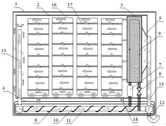
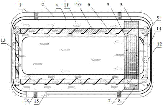
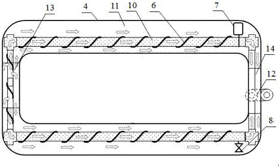
[0036] A medium, energy internal circulation dryer, such as Figure 1-5 As shown, it includes a dryer body 1, a drying chamber 2 and a circulation system, the drying chamber 2 and the circulation system are located inside the dryer body 1, and the circulation system communicates with the drying chamber 2;

[0037] The circulation system includes a fan 5, an evaporator 6, a compressor 7, an expansion valve 8, a condenser 9, a hot air inner flow channel 10, a hot air outer flow channel 11, a U-shaped water outlet pipe 12, a vertical hot air flow channel 13 and a cold air flow Road 14;

[0038] The condenser 9 is installed in the drying chamber 2, and the air outlet of the fan 5 is arranged opposite to the condenser 9, and is used to blow the heat released by the condenser 9 into the drying chamber 2, so as to realize heat circulation in the drying chamber 2;

[0039] The hot-air inner runner 10 is sleeved in the hot-air outer runner 11, the evaporator 6 is evenly distributed on...

Embodiment 2

[0046] A medium and energy internal circulation drying method, using the medium and energy internal circulation dryer described in Embodiment 1, the drying method comprises the following steps:

[0047] A. Put the tray 17 with the material on the loading vehicle 16, and after loading the loading vehicle 16 into the drying chamber 2 from the door 15, close the door 15;

[0048] B. Turn on the heat pump unit 3 and the fan 5, the working medium in the heat pump unit 3 is sucked into the compressor 7 from the evaporator 6 under the action of the compressor 7, and is compressed into a liquid in the condenser 9, and the temperature rises rapidly to generate heat; Then, the working medium enters the evaporator 6 through the expansion valve 8, absorbs heat and cools down the hot air inner flow channel 10 and the hot air outer flow channel 11;

[0049] C. The fan 5 blows cold air into the drying chamber 2 through the condenser 9, and the condenser 9 heats the cold air into hot air; ...


PUM


Abstract

The invention relates to the field of drying equipment, in particular to a medium and energy internal recycle drying machine. The medium and energy internal recycle drying machine is characterized by comprising a drying machine body (1), a drying room (2) and a circle system; and the circle system comprises a draught fan (5), an evaporator (6), a compressor (7), an expansion valve (8), a condenser (9), a hot air internal flow passage (10), a hot air external flow passage (11), a water outlet pipe (12), a vertical hot air passage (13) and a cold air passage (14). According to the provided drying machine, in the drying process, a drying medium and heat energy of a process system recycle in the drying machine and are not discharged outside, the heat loss of exhausted gas does not exist, the material overheating phenomenon cannot occur, the drying process is gentle and stable, the drying quality is good, and the drying energy consumption is greatly saved; and meanwhile, the heat exchanging efficiency of a condensation room is greatly improved, the dehumidifying effect is intensified, and the ventilation power consumption is lowered.

Description

technical field [0001] The invention relates to the field of design drying equipment, and more specifically relates to a medium, energy internal circulation drying method and a dryer. Background technique [0002] Drying is a high-energy-consuming unit operation. Its basic methods mainly include static layer drying and fluidized layer drying, including downstream, countercurrent, cross-flow, and mixed-flow dryers. However, the current drying method is to heat the air and then send it into the The drying layer provides the material with the heat energy needed for water evaporation and absorbs the water, and then discharges it to the outside. The main disadvantage of this method is that the heat energy provided to the drying system is exhausted together with the air, the exhaust heat loss is very large, the exhaust gas pollutes the environment, and the power consumption of ventilation is also very large. At the same time, the drying temperature is not easy to control, and the ...

Claims


Application Information

Patent Timeline
Patent Type & Authority Applications(China)
IPC IPC(8): F26B9/06F26B21/00F26B21/04F25B41/06F25B41/31
CPCF26B9/066F26B21/001F26B21/04F25B41/31
Inventor 李长有郑菲方壮东
Owner SOUTH CHINA AGRI UNIV
Why Eureka
Try Eureka