
Trigger and generator voltage regulator

A voltage regulator and trigger technology, applied in the field of control, can solve problems such as long overcurrent peak time, reduced regulator service life, power tube overcurrent damage, etc., to achieve safety and reliability assurance, improve idle speed stability, reduce Effect of small ripple factor

Active Publication Date: 2016-05-11
西安丝路知星科技服务有限公司
View PDF10 Cites 7 Cited by
  • Summary
  • Abstract
  • Description
  • Claims
  • Application Information

AI Technical Summary

Problems solved by technology

Although the delay time is short, its delay time corresponds to a larger electrical angle, making the generator work in an overvoltage excitation state that should not occur, especially at high speeds, it will cause a larger current and even lead to a larger The load-dumping voltage poses a threat to the regulator and other electrical equipment. Over time, it will cause premature damage to the automotive generator, especially the voltage regulator, and reduce the service life; and most of the existing voltage regulators are triggered by non-fixed frequency. This will lead to instability of the output voltage and high ripple coefficient; in addition, the edge of the excitation waveform output by the existing voltage regulator is not steep, and there are many clutter, resulting in high loss of the device, high temperature, easy damage, and reduced service life. ;
[0005] (2) The trigger in the existing voltage regulator, especially the fixed-frequency excitation circuit, has a complex structure, is difficult to implement, high in cost, large in size and generates a lot of heat, which affects the performance of the entire generator;
[0006] (3) Since the automobile generator operates in a high-temperature and harsh environment, the leakage and short-circuit failure rate caused by the rotor and carbon brush are relatively high, which makes the power tube in the regulator more prone to over-current damage, and it is necessary to set the over-current protection circuit to protect
However, in the existing overcurrent protection circuit, the overcurrent peak time is too long, the protection action lags behind in time, the circuit is more complex, generates more heat, and the protection start and control time is unstable and inaccurate. Even if the overcurrent protection circuit is set, the power tube Still prone to damage due to overcurrent, reducing regulator life

Method used


Image

  • Trigger and generator voltage regulator
  • Trigger and generator voltage regulator
  • Trigger and generator voltage regulator

Examples


Embodiment Construction

[0052] The specific implementation manners of the present invention will be further described in detail below in conjunction with the accompanying drawings and embodiments. The following examples are used to illustrate the present invention, but are not intended to limit the scope of the present invention.

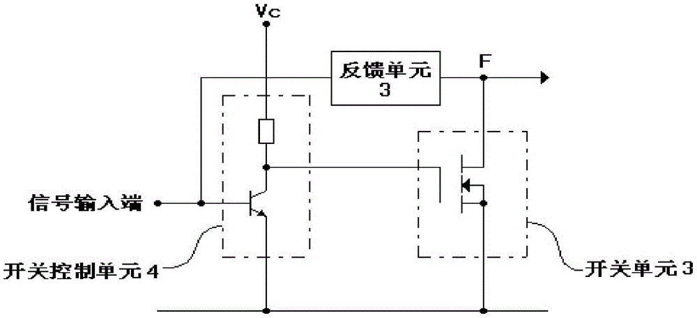
[0053] An embodiment of the present invention provides a trigger and a voltage regulator for a generator. The trigger provided by the present invention will be firstly described below with reference to the accompanying drawings.

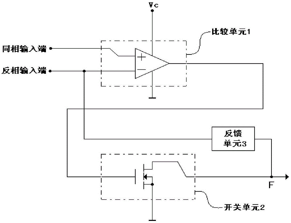
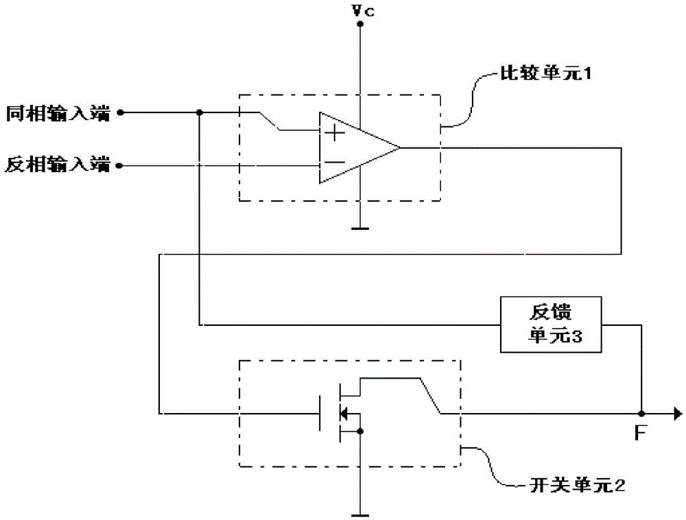
[0054] First aspect, such as figure 1 as shown, figure 1 The first type of flip-flop provided by the embodiment of the present invention is shown, including a comparison unit 1 , a switch unit 2 and a feedback unit 3 .

[0055] Wherein, the comparison unit 1 is connected to the switch unit 2, and is used to output the first voltage to the switch unit 2 when the non-inverting input terminal voltage is greater than the inverting input terminal vo...


PUM


Abstract

The invention provides a trigger and a generator voltage regulator. The trigger comprises a comparison unit, which is connected with a power supply end, ground and a switch unit and is used for outputting a first voltage to the switch unit when the voltage at an in-phase input end is larger than that of an inverse-phase input end, and outputting a second voltage to the switch unit when the voltage at the in-phase input end is smaller than that of the inverse-phase input end; the switch unit, which is connected with the ground or the positive pole of a power supply and a trigger control end, and is used for enabling the control end to be conducted with the ground under the control of the comparison unit, or enabling the control end to the conducted with the positive pole of the power supply; and a feedback unit, which is connected with the control end and the inverse-phase input end of the comparison unit, and is used for positively feeding back the signal of the control end to the inverse-phase input end of the comparison unit. When the trigger is applied to the voltage regulator, integration of multiple functions of excitation fixed-frequency triggering, immediate overvoltage cutting off and over-current protection is realized; and a sampling circuit does not need a capacitor, and synchronous detection and overvoltage excitation cut off are realized, and overtime overvoltage excitation does not occur, so that the effects of stable voltage, accurate adjustment and being safe and reliable are achieved, and the service life of the regulator and the service life of a generator are prolonged.

Description

technical field [0001] The invention relates to the technical field of control, in particular to a trigger and a generator voltage regulator. Background technique [0002] The power supply of a car generally consists of two parts: a generator and a battery. The automobile alternator is driven by the automobile engine to generate direct current or alternating current during the operation of the automobile to provide the electric energy required by the automobile. Generally, an excitation type alternator is used. This kind of generator controls the power generation through the excitation coil, and a voltage regulator is set accordingly. When the output voltage of the generator (that is, the voltage output by the positive pole of the power supply) is higher than the set threshold Cut off the excitation current on the coil when the voltage is high. [0003] Yet there are following three problems in existing automobile generator voltage regulator (hereinafter referred to as vol...

Claims


Application Information

Patent Timeline
Patent Type & Authority Applications(China)
IPC IPC(8): H02P9/30
CPCH02P9/305H03F1/523
Inventor 杨明
Owner 西安丝路知星科技服务有限公司
Learn More