Clock signal source with low phase noise and adjustable duty cycle

A clock signal and duty cycle technology, applied in the direction of automatic power control, instrumentation, electrical digital data processing, etc., can solve the problem that the phase noise of the output clock does not meet the requirements, so as to reduce the production test cost, improve the test efficiency, Optimizing the effect of the test setup

Inactive Publication Date: 2017-07-18
NO 24 RES INST OF CETC
View PDF5 Cites 4 Cited by
  • Summary
  • Abstract
  • Description
  • Claims
  • Application Information

AI Technical Summary

Problems solved by technology

Traditional clock signal sources cannot effectively guarantee that the above two parameters meet the requirements at the same time. Some clock signal sources meet the phase noise requirements, but can only provide a clock signal with a fixed duty cycle of 50%; The ratio is adjustable, but the output clock phase noise does not meet the requirements

Method used


Image

  • Clock signal source with low phase noise and adjustable duty cycle
  • Clock signal source with low phase noise and adjustable duty cycle
  • Clock signal source with low phase noise and adjustable duty cycle

Examples


Embodiment Construction

[0028] The preferred embodiments of the present invention will be described in detail below in conjunction with the accompanying drawings; it should be understood that the preferred embodiments are only for illustrating the present invention, rather than limiting the protection scope of the present invention.

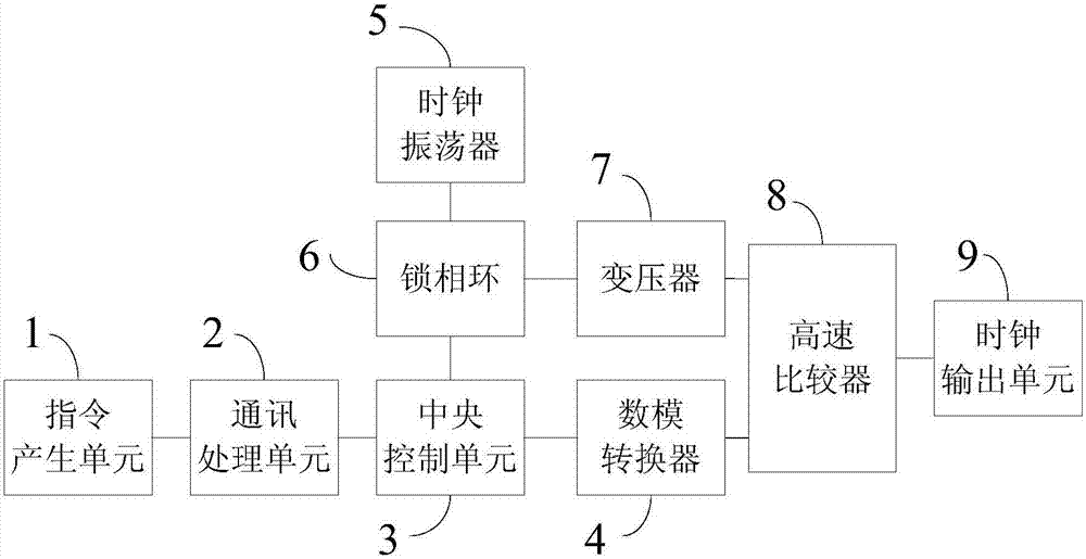
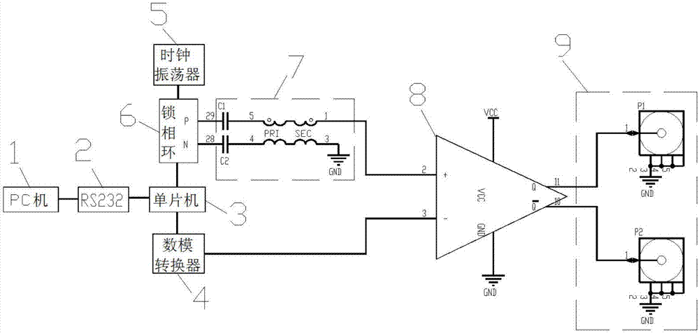
[0029] Please refer to figure 1 As shown, the present invention provides a clock signal source with low phase noise and adjustable duty ratio, including an instruction generation unit 1, a communication processing unit 2, a central control unit 3, a digital-to-analog converter 4, a clock oscillator 5, and a phase-locked loop 6. Transformer 7, high-speed comparator 8 and clock output unit 9; wherein,

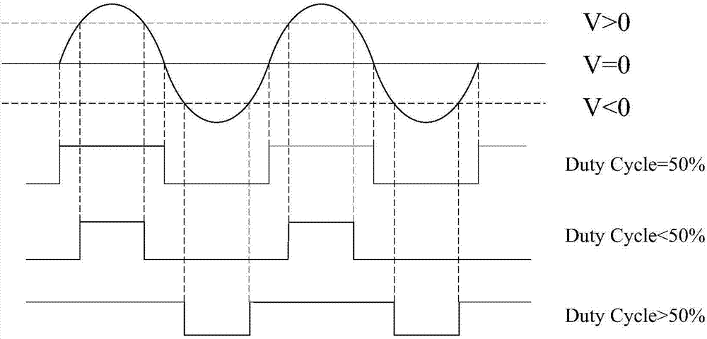
[0030] Instruction generation unit 1: used to generate control signal instructions for controlling the duty cycle and frequency of the output clock;

[0031] The communication processing unit 2: receives the control signal command from the command generation unit 1, and e...


PUM


Abstract

The invention discloses a clock signal source with low phase noise and adjustable duty cycle. The clock signal source comprises an instruction generation unit, a communication processing unit, a central control unit, a digital-to-analog converter, a phase-locked loop, a clock oscillator, a transformer and a high-speed comparator, wherein the instruction generation unit is used for generating a control signal instruction that controls the output clock duty cycle and frequency; the communication processing unit is used for encoding the control signal instruction to generate a control signal bit stream; the central control unit is used for analyzing the specific meaning of the control signal bit stream and generating a corresponding first control bit stream and a second control bitstream; the digital-to-analog converter is used for receiving the first control bit stream and obtaining a first control signal; the phase-locked loop is used for receiving the second control bit stream and generating a differential clock output with adjustable frequency; the clock oscillator is used for providing a low-noise reference frequency source for the phase-locked loop; the transformer is used for converting the differential clock output to a single-end clock output to obtain a second control signal; and the high-speed comparator is used for receiving the first control signal and the second control signal and controlling the clock output unit to output a low-noise clock signal with the set frequency and duty cycle. By adopting the clock signal source disclosed by the invention, the cost of a test system of the digital-to-analog converter can be reduced.

Description

technical field [0001] The invention relates to a clock signal source with low phase noise and adjustable duty ratio, in particular to a clock signal source used in the testing field of high-speed and high-precision analog-to-digital converters. Background technique [0002] With the rapid development of the information technology industry, the application range of analog-to-digital converters is becoming wider and wider, and the performance requirements of analog-to-digital converters are getting higher and higher. The sampling clock is the basic element of the ADC. For the tester or application of the ADC, the clock scheme, clock type, clock voltage level, and clock jitter used by the ADC are very important. The jitter of the sampling clock is a short-term, non-accumulative variable, which represents the time deviation between the actual timing position of the digital signal and its ideal position. Clock jitter will cause the internal circuit of the analog-to-digital conv...

Claims


Application Information

Patent Timeline
Patent Type & Authority Applications(China)
IPC IPC(8): H03K3/017H03L7/08G06F13/42
CPCG06F13/4282G06F2213/0002G06F2213/0042H03K3/017H03L7/08
Inventor 温显超俞宙陈超骆才学李曦李儒章王育新付东兵
Owner NO 24 RES INST OF CETC
Why Eureka
Try Eureka