Ball-milling tank and planetary ball mill with same

A ball milling tank and tank bottom technology, applied in grain processing, etc., can solve the problems of low grinding efficiency, insignificant impact effect, and low grinding quality, and achieve the effect of improving grinding quality, grinding efficiency and performance

Inactive Publication Date: 2017-07-21
NORTHEASTERN UNIV LIAONING
View PDF9 Cites 5 Cited by
  • Summary
  • Abstract
  • Description
  • Claims
  • Application Information

AI Technical Summary

Problems solved by technology

[0003] The inner walls of the ball mill jars used in planetary ball mills in practical applications are all smooth and curved. The grinding action between the ball mill jar and the powder makes the powder crush and mix. The impact effect is not very significant, so the grinding efficiency is low. Grinding quality is not high

Method used


Image

  • Ball-milling tank and planetary ball mill with same
  • Ball-milling tank and planetary ball mill with same
  • Ball-milling tank and planetary ball mill with same

Examples


Embodiment 1

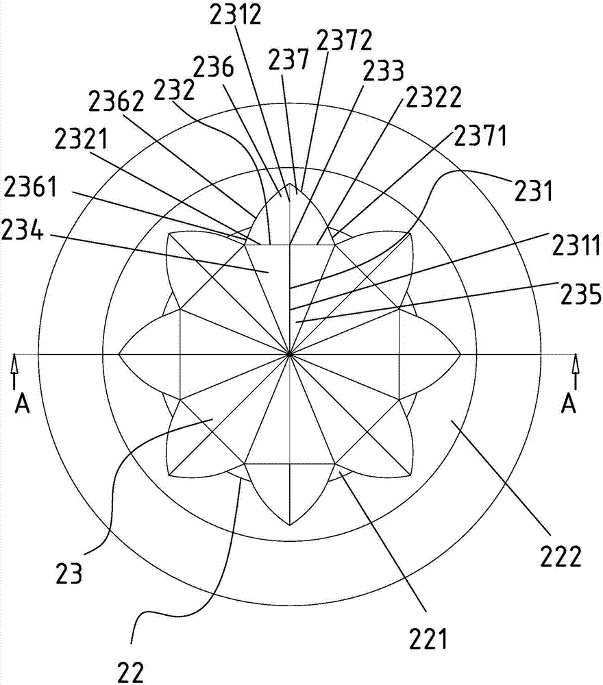
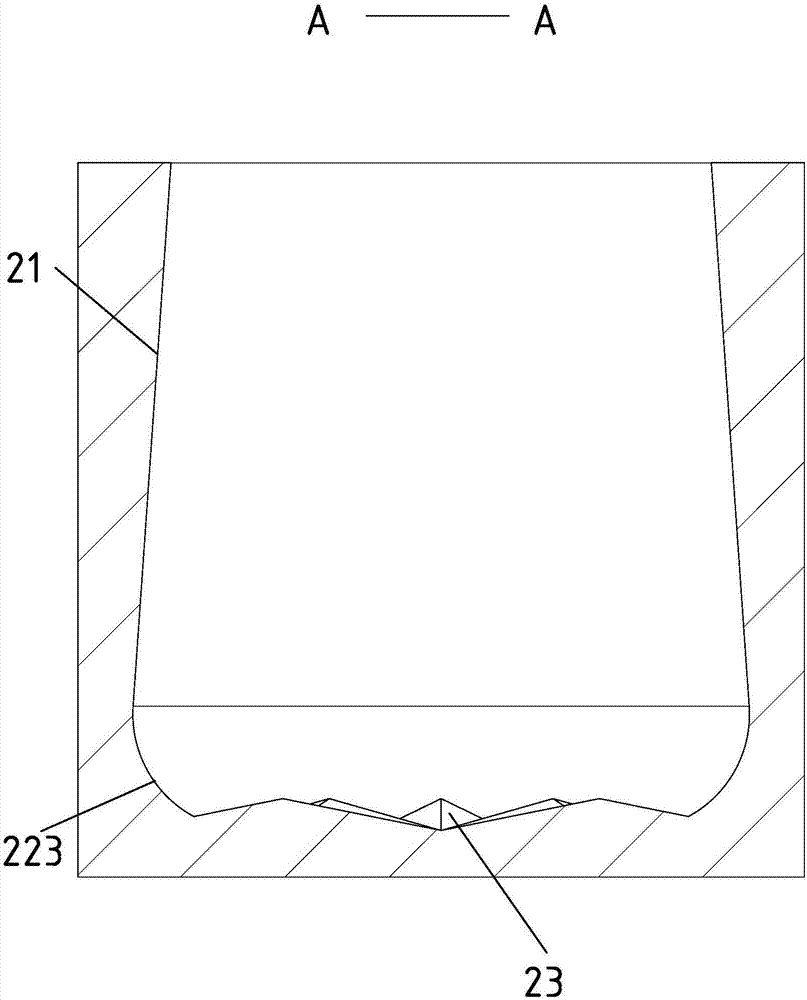
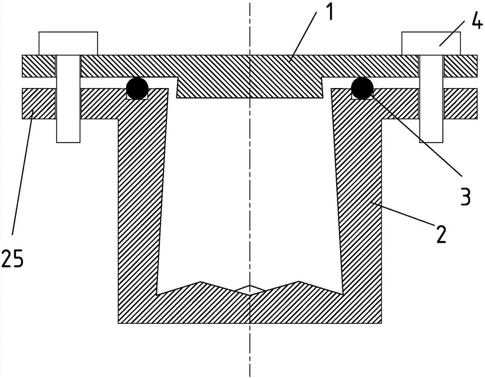
[0032] Such as Figure 1-Figure 4 As shown, a ball milling tank includes a tank cover 1 and a tank body 2, the tank body 2 has a non-cylindrical side wall inner wall 21, and the tank bottom 22 of the tank body 2 has a plurality of tank bottoms 22 The center is the protrusions 23 evenly distributed in the center.

[0033] The orthographic projection of the protrusion 23 on the tank bottom 22 is a kite-like shape 24, and there are common sides between adjacent kite-like shapes 24, that is, each of the kite-like shapes 24 includes A common side I241 and a common side II242, one end of the common side I241 and the common side II242 coincides with the center of the tank bottom 22, and the other end is located at the end of the asymmetrical axis diagonal line 243 of the kite-like shape 24;

[0034] The protrusion 23 has a symmetrical edge 231 corresponding to the symmetric axis diagonal line 244 of the kite-like shape 24 and an asymmetric edge 232 corresponding to the asymmetric ax...

Embodiment 2

[0048] Such as Figure 5 As shown, a planetary ball mill containing the ball mill jar described in Example 1 includes a drive motor 5, a transmission mechanism 6, a revolving turntable 7 located on the transmission mechanism 6, and a plurality of revolving turntables 7 located on the revolving turntable 7 The rotation shaft 8 on the top, the said rotation shaft 8 is provided with the ball mill jar as described in embodiment 1, the output end of the said driving motor 5 is connected with the input end of the said transmission mechanism 6 through the belt pulley 9, the said rotation shaft 8 The axis is parallel to and not coincident with the axis of the ball mill jar.

[0049] Use the ball mill jar described in Example 1 and the same material ball mill jar (contrast ball mill jar) that the inner wall of the side wall is a smooth cylindrical surface to grind the limestone blocks that are 300g in quality and have the same shape, stop every 60 seconds, and use A 200-mesh sieve scr...


PUM


Abstract

The invention discloses a ball milling jar and a planetary ball mill containing the ball milling jar. The ball milling jar includes a jar cover and a jar body. The jar body has a non-cylindrical side wall and an inner wall. A plurality of protrusions are evenly distributed around the center of the tank bottom. The present invention designs the tank bottom of the ball mill tank as a diamond-shaped protrusion, increases the contact area between the tank bottom and the abrasive, makes the tank bottom a fixed grinding ball, and participates in the grinding process of the abrasive; increases the contact area between the tank bottom and the abrasive. Friction, and greatly increase the impact force and impact frequency of the abrasive. The inner wall of the side wall of the ball mill tank is designed as a non-cylindrical side wall inner wall, so that the abrasive material is pushed to the bottom of the tank under the action of centrifugal force to increase the grinding effect of the protrusion on the abrasive material, so that the grinding efficiency of the planetary ball mill can be improved. And the grinding quality has been greatly improved, improving the performance of the original planetary ball mill.

Description

technical field [0001] The invention relates to the field of planetary ball milling devices, in particular to a ball milling pot and a planetary ball mill containing the ball milling pot. Background technique [0002] Ball mill is a common mechanical device for producing ultra-fine powder. At present, ball milling method is widely used in mineral processing, powder preparation and ceramic processing. It has a good effect on the grinding, fine grinding and fine grinding of powder materials. , The ball milling method has the characteristics of simple process and remarkable effect. [0003] At present, the inner wall of the ball mill tank used in the planetary ball mill in practical application is smooth and curved. The grinding action between the ball mill tank and the powder makes the powder body pulverized and mixed. The impact effect is not very significant, so the grinding efficiency is low. Grind quality is not high. Contents of the invention [0004] According to the...

Claims


Application Information

Patent Timeline
Patent Type & Authority Applications(China)
IPC IPC(8): B02C17/08
CPCB02C17/08
Inventor 姜盛鑫王佳琪古昭昭彭岳衡刘杰杨敬飞
Owner NORTHEASTERN UNIV LIAONING
Why Eureka
Try Eureka