
Mining classification device

A classification device and mine technology, applied in solid separation, separation of solids from solids by air flow, chemical instruments and methods, etc., can solve the blockage of the discharge port, the impact of the discharge port on the classification accuracy, and the normal operation of the classification device. and other problems, to achieve the effect of narrow particle size distribution and high classification accuracy

Inactive Publication Date: 2017-07-21
江西省浩燃冶金设备有限责任公司
View PDF4 Cites 0 Cited by
  • Summary
  • Abstract
  • Description
  • Claims
  • Application Information

AI Technical Summary

Problems solved by technology

In the classification process, the separation of ore particles is mainly carried out during the flow process from the ore feeding point to the overflow point. The larger ore particles settle in the middle, and gradually settle according to the particle size of the ore particles, and finally fine The ore flow of the ore flows to the overflow outlet, and at the same time, the fine-grained overflow and the coarse-grained sand return are obtained. Most of the existing hydraulic classification devices have a single cylinder structure, and only two coarse-grained sediments and undercurrents can be obtained at a time. , fine products, and the classification effect is not good, it is easy to cause blockage of the discharge port. The blockage of the discharge port not only affects the classification accuracy, but also needs to be shut down for cleaning and maintenance, which affects the normal operation of the grading device.

Method used


Image

  • Mining classification device
  • Mining classification device

Examples


Embodiment Construction

[0014] The technical solutions in the embodiments of the present invention will be further clearly and completely described below in conjunction with the embodiments and the accompanying drawings.

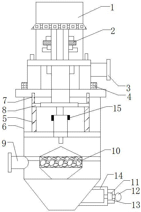
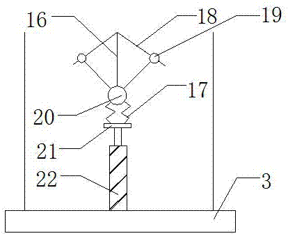
[0015] see figure 1 , figure 1 It is a schematic structural view of the present invention, a mining classification device, including a body 6 and a discharge port 3, the body 6 of the single-stage classification device is provided with an inspection door, and the inspection door is in the same position as the classification wheel 5 Correspondingly, the discharge port 3 includes a support rod 22, a fixed plate 21 is installed above the support rod 22, a spring 17 is arranged above the fixed plate 22, and a second hinge device 20 is installed above the spring 17, so that A second sliding rod 16 is installed above the second hinge device 20, a first hinge device 19 is installed on the right side of the second sliding rod 16, and a first sliding rod 18 is installed above the first hin...


PUM


Abstract

The invention discloses a mining classification device which comprises a machine body and a discharging opening. The machine body comprises a classification wheel. A second labyrinth ring is mounted above the classification wheel. A first labyrinth ring is mounted above the second labyrinth ring. A gas inlet channel is mounted above the first labyrinth ring. The discharging opening is formed above the gas inlet channel. A variable frequency motor is mounted above the discharging opening. A feeding opening is formed in the left side of an inner barrel. A secondary air inlet device is mounted below the inner barrel and comprises a pore plate. A cover plate is mounted on the right side of the pore plate. A locking device is mounted on the right side of the cover plate. According to the mining classification device, the technical problems about classification precision and sealing between the classification wheel and the machine body are solved; the mining classification device is widely applied to fine classification of solid particles; through the arrangement of an anti-blockage device, the effects that high-precision classification sedimentation can be carried out on ore particles in ore pulp, and the discharging opening is not prone to being blocked by the ore particles are achieved; and the mining classification device is worthy of energetic popularization.

Description

technical field [0001] The invention belongs to the technical field of grading devices, and in particular relates to a mining grading device. Background technique [0002] At present, the domestic mine grinding and grading equipment basically adopts the spiral grading device, which has low grading efficiency, high equipment energy consumption, high maintenance labor intensity, and high production and maintenance costs. Especially when the nature of the ore is that the strong magnetic minerals and weak magnetic minerals alternate or wrap each other, the weak magnetic minerals must be in the form of a joint body with the strong magnetic minerals to be effectively recovered, so it is not suitable to grind too finely, otherwise the weak magnetic minerals cannot be recovered. However, due to the low classification efficiency of the spiral classification device, some minerals are over-grinded or even seriously muddled, which is not conducive to the recovery of magnetic minerals, w...

Claims


Application Information

Patent Timeline
Patent Type & Authority Applications(China)
IPC IPC(8): B07B7/083B02C23/20
CPCB07B7/083B02C23/20
Inventor 赖平连
Owner 江西省浩燃冶金设备有限责任公司
Learn More