Welding working station of air conditioner condenser
A technology for welding workstations and air-conditioning condensers, applied in welding equipment, welding equipment, auxiliary welding equipment, etc., can solve the problems of large occupation area, high equipment cost, and reduced processing efficiency, and achieve the effect of preventing misalignment and fine welding
- Summary
- Abstract
- Description
- Claims
- Application Information
AI Technical Summary
Problems solved by technology
Method used
Image

Examples
Embodiment Construction
[0022] The present invention will be described in further detail below in conjunction with the embodiments given in the accompanying drawings.
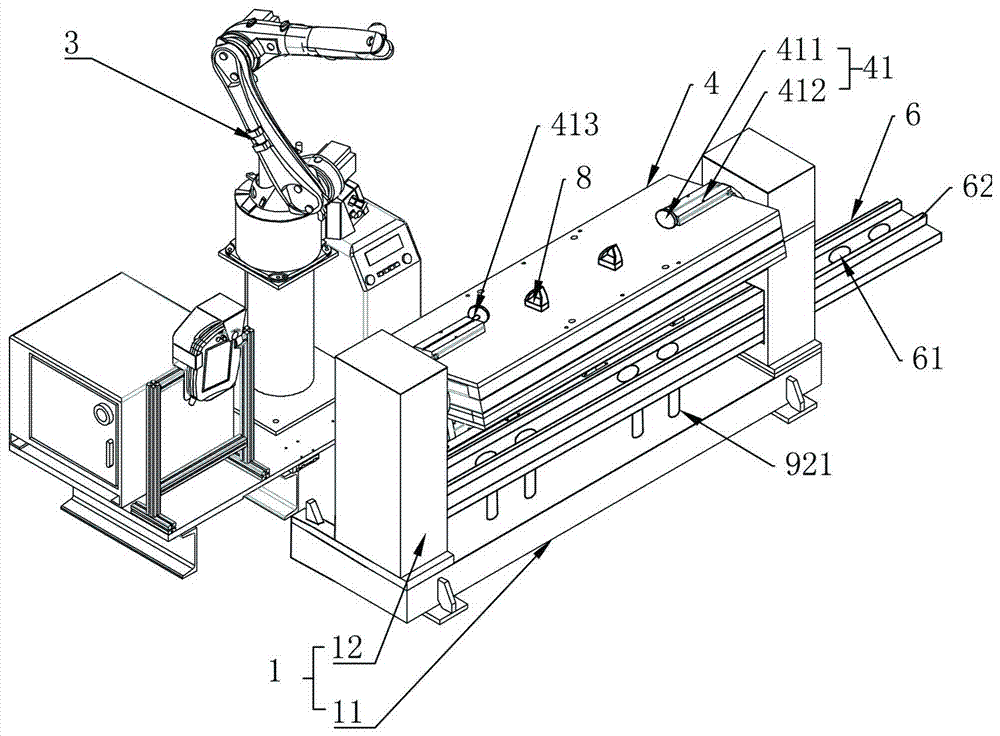
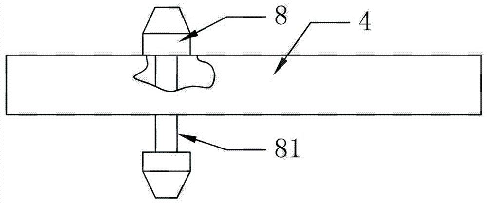
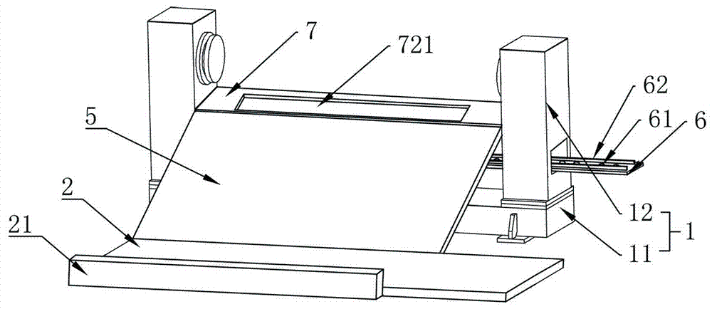
[0023] refer to Figures 1 to 7As shown, a welding workstation for an air conditioner condenser in this embodiment includes a variable camera 1, a guide belt 5, a guide plate 7, an incoming belt 6, a conveyor belt 2, a pneumatic telescopic rod 921 and a welding robot 3, and the variable camera 1 is provided with a workbench 4, and the variable camera 1 controls the rotation of the worktable 4. The variable camera 1 includes a base 11 and two oppositely arranged pillars 12, and one end of the two pillars 12 is connected to two ends of the base 11 respectively. The ends are fixedly connected, and the two ends of the workbench 4 are respectively rotatably connected with two pillars 12. The welding robot 3 is arranged on one side of the transformer 1 and is arranged near the middle of the workbench 4. The workbench 4, The guide plate 7, ...
PUM
 Abstract
Description
Claims
Application Information
 - R&D
- Intellectual Property
- Life Sciences
- Materials
- Tech Scout
- Unparalleled Data Quality
- Higher Quality Content
- 60% Fewer Hallucinations
Browse by: Latest US Patents, China's latest patents, Technical Efficacy Thesaurus, Application Domain, Technology Topic, Popular Technical Reports.
© 2025 PatSnap. All rights reserved.Legal|Privacy policy|Modern Slavery Act Transparency Statement|Sitemap|About US| Contact US: help@patsnap.com