A magneto-rheological torsional vibration damper for an engine

A torsional vibration damper and magneto-rheological technology, applied in the direction of shock absorbers, shock absorbers, springs/shock absorbers, etc., can solve problems such as shortened service life, unstable power supply, and increased energy loss, and achieve Adaptive damping force, relatively low cost, and the effect of adjusting the damping force

Active Publication Date: 2018-12-04
NINGBO UNIV
View PDF8 Cites 0 Cited by
  • Summary
  • Abstract
  • Description
  • Claims
  • Application Information

AI Technical Summary

Problems solved by technology

[0004] However, there are the following problems in the magneto-rheological torsional vibration damper of the above-mentioned engine: one, the damper is only an actuator, and it cannot control the magnetic field change according to the real-time speed of the engine. It must be equipped with a detection and control system to detect the real-time speed of the engine, and The control power supply generates corresponding voltage signals to realize the change of the magnetic field. The system is huge and complex, which leads to high cost of the vibration reduction system; The grinding bush can be rotated, so a clearance fit must be adopted between the two (there is a gap in most areas, and some parts are in contact with electricity), and the crankshaft will have periodic large-intensity radial runouts during high-speed operation, which will affect the The inertial ring produces frequent large-load rigid impacts. On the one hand, it will cause fatigue failure of the inertial ring and shorten the service life. Real-time changes will lead to unstable power supply; 3. The gap between the inertial ring and the annular wear-reducing bushing will cover a layer of damping liquid film on the surface of the inertial ring and the annular wear-reducing bushing in actual operation. It is an insulating liquid. When the input current passes through the damping liquid film, a large amount of heat will be generated, which will hinder the passage of current and increase energy loss.

Method used


Image

  • A magneto-rheological torsional vibration damper for an engine
  • A magneto-rheological torsional vibration damper for an engine
  • A magneto-rheological torsional vibration damper for an engine

Examples


Embodiment 1

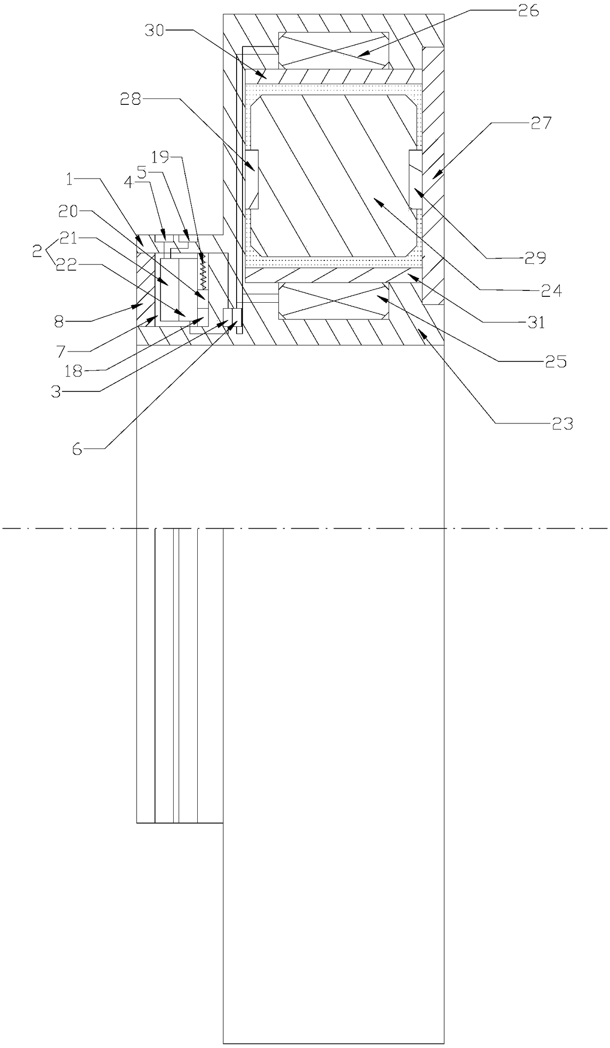
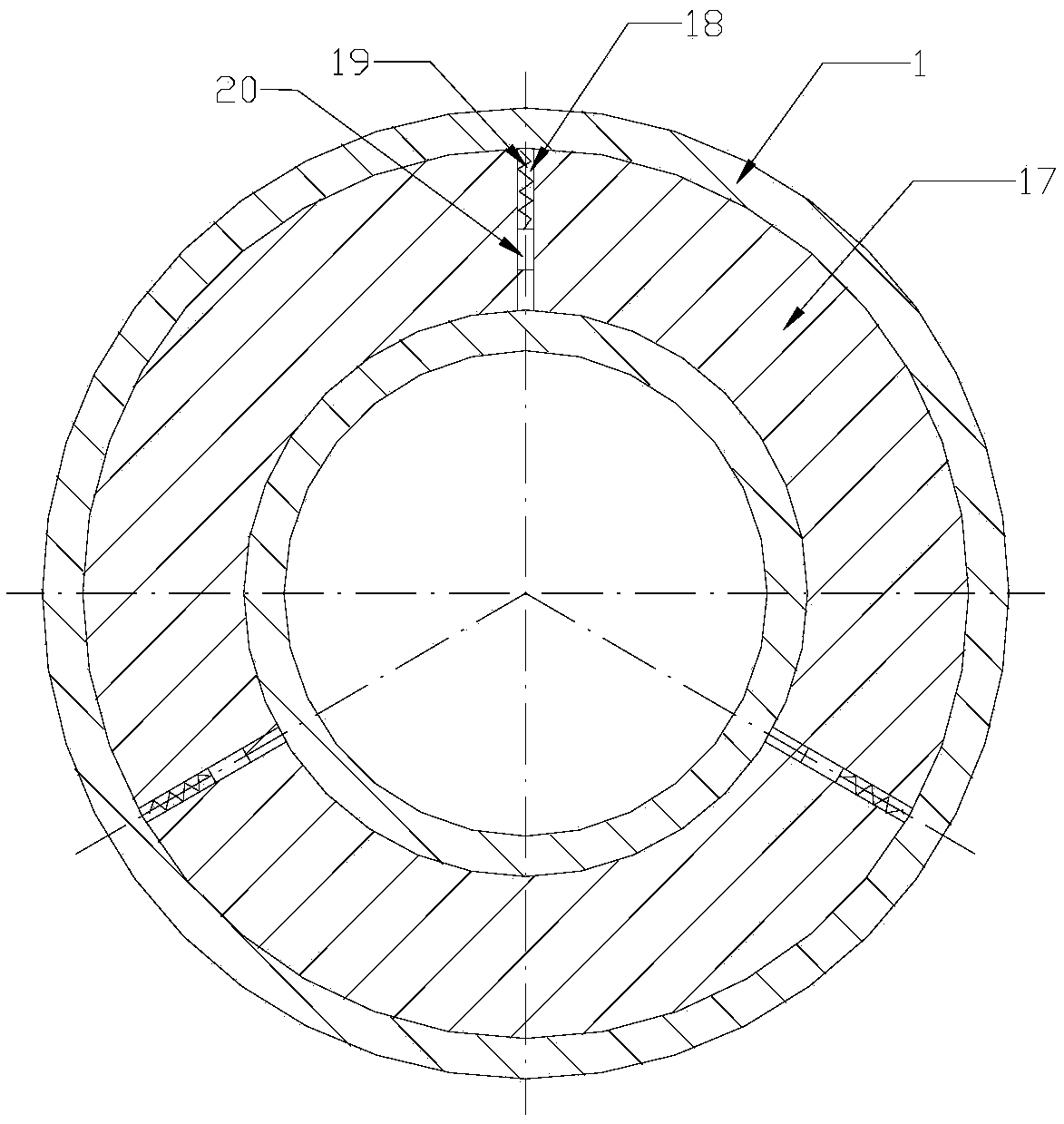
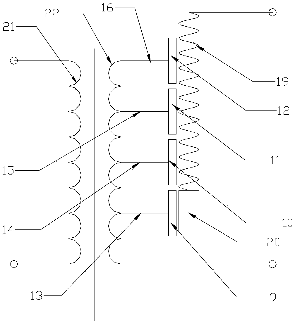
[0015]Embodiment 1: As shown in the figure, an engine magneto-rheological torsional vibration damper includes a main structure of the magnetorheological torsional vibration damper, and the engine magnetorheological torsional vibration damper also includes an adaptive voltage regulation module, The adaptive voltage regulation module includes a first annular casing 1, a control transformer 2, a voltage comparator 3, a first collector ring 4, a second collector ring 5, an AC-DC converter 6 and an adaptive brush assembly, the voltage The comparator 3 has a first input terminal, a second input terminal, a third input terminal, a fourth input terminal and an output terminal, and the first slip ring 4 and the second slip ring 5 are arranged on the first annular casing 1 respectively. On the outer wall, the first annular housing 1 is provided with a first annular cavity 7 with an open left end, and the opening of the first annular cavity 7 is provided with a first cover plate 8 coverin...

Embodiment 2

[0016] Embodiment 2: As shown in the figure, an engine magneto-rheological torsional vibration damper includes a main structure of the magnetorheological torsional vibration damper, and the engine magnetorheological torsional vibration damper also includes an adaptive voltage regulation module, The adaptive voltage regulation module includes a first annular casing 1, a control transformer 2, a voltage comparator 3, a first collector ring 4, a second collector ring 5, an AC-DC converter 6 and an adaptive brush assembly, the voltage The comparator 3 has a first input terminal, a second input terminal, a third input terminal, a fourth input terminal and an output terminal, and the first slip ring 4 and the second slip ring 5 are arranged on the first annular casing 1 respectively. On the outer wall, the first annular housing 1 is provided with a first annular cavity 7 with an open left end, and the opening of the first annular cavity 7 is provided with a first cover plate 8 coveri...

Embodiment 3

[0018] Embodiment 3: As shown in the figure, an engine magneto-rheological torsional vibration damper includes a main structure of the magnetorheological torsional vibration damper, and the engine magnetorheological torsional vibration damper also includes an adaptive voltage regulation module, The adaptive voltage regulation module includes a first annular casing 1, a control transformer 2, a voltage comparator 3, a first collector ring 4, a second collector ring 5, an AC-DC converter 6 and an adaptive brush assembly, the voltage The comparator 3 has a first input terminal, a second input terminal, a third input terminal, a fourth input terminal and an output terminal, and the first slip ring 4 and the second slip ring 5 are arranged on the first annular casing 1 respectively. On the outer wall, the first annular housing 1 is provided with a first annular cavity 7 with an open left end, and the opening of the first annular cavity 7 is provided with a first cover plate 8 coveri...


PUM


Abstract

The invention discloses a magneto-rheological torsional vibration absorber of an engine. The magneto-rheological torsional vibration absorber of the engine comprises a magneto-rheological torsional vibration absorber body structure and a self-adapting pressure regulating module, wherein the self-adapting pressure regulating module comprises a first annular housing, a control transformer, a voltage comparator, a first collecting ring, a second collecting ring, an AC-DC converter and a self-adapting electric brush assembly; the voltage comparator comprises a first input end, a second input end, a third input end, a fourth input end and an output end; the first collecting ring and the second collecting ring are correspondingly arranged on the outer sidewall of the first annular housing; a first annular concave chamber which is provided with an opening in the left end is arranged on the first annular housing; a first covering plate is arranged at the opening of the first annular concave chamber and can cover the opening. The magneto-rheological torsional vibration absorber of the engine has the advantages that the damping force can be self-adaptively adjusted; the cost is relatively low; frequent high-load rigid impact on an inertia circular ring is avoided; the power is stably supplied; and moreover, the energy loss is small.

Description

technical field [0001] The invention relates to a shock absorber, in particular to a magneto-rheological torsional vibration shock absorber for an engine. Background technique [0002] As the torsional elastic system of the engine, the crankshaft is usually formed by connecting several crank throws in sequence. In the high-speed operation of the engine (such as a diesel engine), the crankshaft inevitably has a certain natural vibration frequency, and the crankshaft will bear the disturbance torque generated by the gas pressure, and the magnitude and direction of the disturbance torque change periodically, resulting in crankshaft The change in instantaneous angular velocity. Since the rear end of the crankshaft is equipped with a flywheel, the flywheel has a large inertia, so the instantaneous angular velocity of the flywheel can be considered uniform. At this time, the crankshaft will produce relative torsional swing to the flywheel, that is, torsional vibration. When the ...

Claims


Application Information

Patent Timeline
Patent Type & Authority Patents(China)
IPC IPC(8): F16F9/53F16F15/03
CPCF16F9/535F16F15/035
Inventor 冯志敏董致臻张刚胡海刚陈跃华
Owner NINGBO UNIV
Why Eureka
Try Eureka