Eureka AIR delivers breakthrough ideas for toughest innovation challenges, trusted by R&D personnel around the world.

Two-phase mixing reactor and applications thereof

A mixed reactor and reactor technology, applied in chemical/physical/physicochemical fixed reactors, chemical instruments and methods, refining with alkaline aqueous solution, etc., can solve low mass transfer coefficient, fiber filament pollution, mass transfer Efficiency reduction and other problems, to achieve the effect of enhanced mass transfer performance, strong pressure resistance, and easy sealing

Active Publication Date: 2017-07-25
CHINA PETROLEUM & CHEM CORP +1
View PDF4 Cites 0 Cited by
  • Summary
  • Abstract
  • Description
  • Claims
  • Application Information

AI Technical Summary

Problems solved by technology

[0005] The extraction column is a continuous countercurrent equipment that can achieve multiple theoretical levels of separation efficiency, but its equipment scale is large, the operation is relatively complicated, and the material flow rate is slow and the mass transfer coefficient is low.
[0006] The fiber membrane extractor is a kind of co-current operation equipment. Its equipment scale is smaller than that of the extraction tower, and the hydrophilic fiber filaments are used to provide a larger mass transfer area, so the mass transfer efficiency is higher, but the fiber filaments will be damaged after long-term use. Contaminated to lose hydrophilicity, lower mass transfer efficiency, and difficult to clean and regenerate
[0007] The static mixer has the smallest equipment scale and relies on two-phase high-speed flow mixing for mass transfer. However, the mixing structure of the static mixer is difficult to achieve highly dispersed mixing of the liquid / liquid system, so there is still a large bottleneck in the improvement of its mass transfer efficiency.

Method used


Image

  • Two-phase mixing reactor and applications thereof
  • Two-phase mixing reactor and applications thereof
  • Two-phase mixing reactor and applications thereof

Examples


Embodiment 1

[0088] In this embodiment, the two-phase mixed reactor described in the present invention is used to desulfurize light hydrocarbons, specifically as follows:

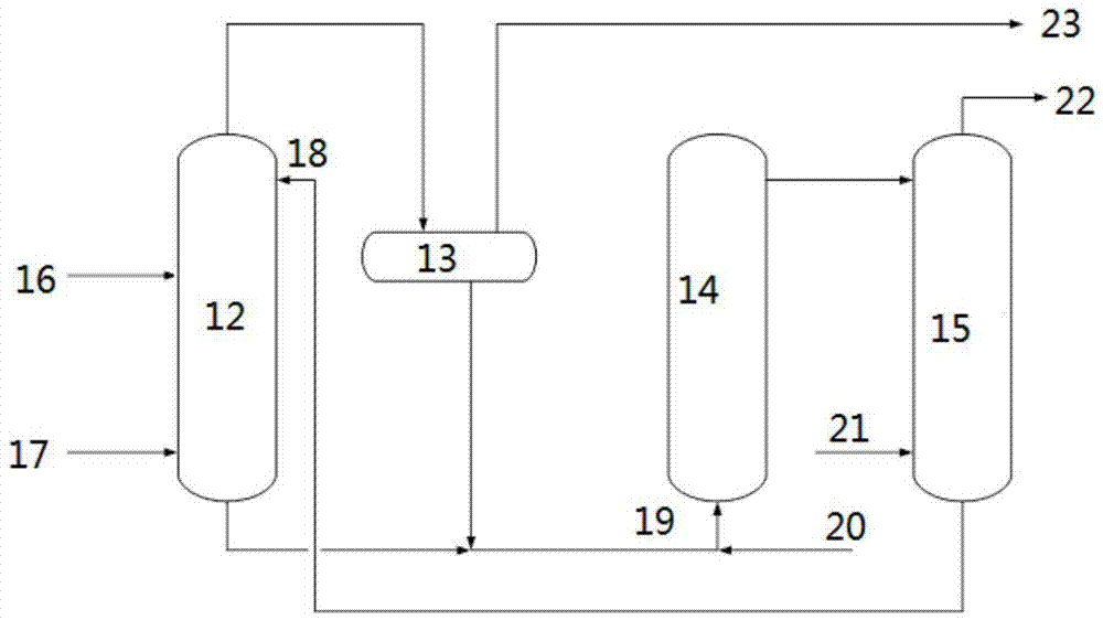
[0089] The liquefied petroleum gas containing mercaptan and the alkali solution contact in the alkali cleaning unit, and the mercaptan reacts with the NaOH in the alkali solution to form sodium mercaptide which is dissolved in the alkali solution. The liquefied gas discharged from the alkaline cleaning unit enters the settling unit and is separated from part of the alkali liquor entrained to complete the purpose of sweetening. The lye discharged from the settling unit enters the oxidation regeneration unit, and in the packed bubbling bed reactor, the lye reacts with air to convert sodium mercaptide into disulfide. The desulfurized lye discharged from the oxidation regeneration unit enters the back extraction unit, contacts with gasoline, removes the entrained disulfide, and obtains the regenerated lye. The regenerated ...

Embodiment 2

[0100] In this embodiment, the two-phase mixed reactor described in the present invention is used to desulfurize light hydrocarbons, specifically as follows:

[0101] The light hydrocarbon desulfurization method in this embodiment is similar to that in Example 1, and the two-phase mixed reactor also includes 11 groove structures, the difference is:

[0102] The light hydrocarbon in this example is light gasoline, and there is only one two-phase mixed reactor in the alkali washing unit and the stripping unit.

[0103] The selected light gasoline was obtained from Jiujiang Petrochemical, and its hydrocarbon volume percentage composition is shown in Table 2.

[0104] Table 2: Volume percentage composition of light gasoline hydrocarbons

[0105] n-paraffin / % Isoparaffin / % Olefin / % Diene / % C4 2.141 0.978 5.237 0 C5 13.368 41.388 29.821 0.039 C6 0 5.889 1.140 0

[0106] The total amount of acid mercaptans in light gasoline is determine...

Embodiment 3

[0112] In this embodiment, the two-phase mixed reactor described in the present invention is used to desulfurize light hydrocarbons, specifically as follows:

[0113] The method of light hydrocarbon desulfurization in the present embodiment is similar to that in embodiment 2, difference is:

[0114] In the alkaline cleaning unit: according to the flow direction of the lye in the cavity unit, the diameters of the distribution holes are 1mm, 0.7mm and 0.4mm respectively, the depth of the distribution holes is 1mm, and the distance between the centers of two adjacent distribution holes is 27mm. The cross-sectional area of ​​the cavity unit perpendicular to the flow direction of lye is 280mm 2 , the cross-sectional area of ​​the mixing channel perpendicular to the flow direction of sulfur-containing light hydrocarbons is 6mm 2 , the length of the mixing channel is 1000mm. The temperature in the two-phase mixing reactor was 50° C. and the pressure was 1.2 MPa. The superficial f...


PUM

PropertyMeasurementUnit
Diameteraaaaaaaaaa

Abstract

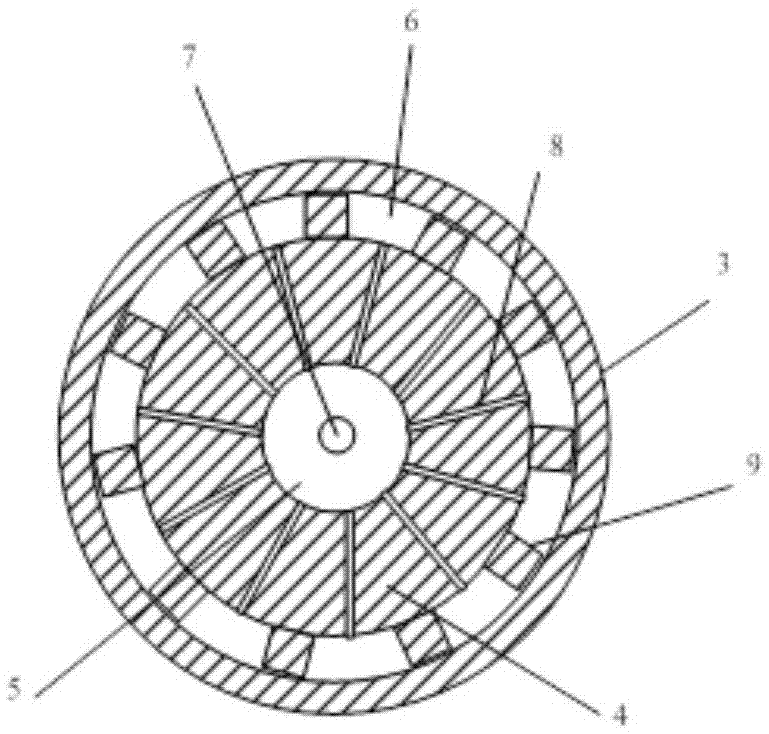
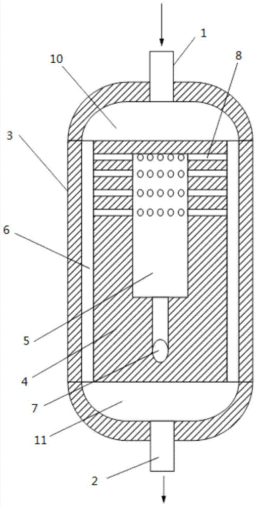
The present invention relates to the field of oil refining, and discloses a two-phase mixing reactor and applications thereof. The two-phase mixing reactor comprises a reactor inlet, a reactor outlet, a reactor tank and a reaction module, wherein the outer surface of the reaction module is provided with a concave groove structure, the projecting side wall of the concave groove structure is connected to the reactor tank, the cavity enclosed by the concave groove structure and the reactor tank forms a mixing flow channel, a cavity unit is arranged in the reaction module and is communicated to the mixing flow channel through the distribution holes arranged on the bottom portion of the concave groove structure of the reaction module, and the flowing direction of a fluid in the cavity unit is opposite to the flowing direction of the fluid in the mixing flow channel due to the arrangement of the inlet of the cavity unit. According to the present invention, with the application of the two-phase mixing reactor in the deep desulfurization of light hydrocarbons, the light hydrocarbon and the alkali liquid flow at the high speed and are intensely mixed, the mass transfer resistance is low, the deep desulfurization is achieved, the acidic sulfur-containing substance removal rate is more than 90%, and the acidic sulfur-containing substance concentration in the liquefied gas can be reduced to less than 10 ppm or less.

Description

technical field [0001] The invention relates to the field of oil refining, in particular to a two-phase mixed reactor and the application of the two-phase mixed reactor in liquid / liquid two-phase or gas / liquid two-phase mixing and reaction. Background technique [0002] The crude liquefied gas produced by the refinery contains a large amount of acidic sulfur-containing substances (mainly hydrogen sulfide and mercaptans), and the acidic sulfur-containing substances are generally removed by alkaline washing in industry. [0003] The liquefied gas can be used to produce clean fuel after deep desulfurization (the concentration of acidic sulfur-containing substances is below 10ppm). However, it is difficult for conventional liquefied gas desulfurization equipment to overcome the mass transfer resistance in the deep desulfurization process under the condition that the operating conditions are basically unchanged. Liquefied gas deep desulfurization requirements. [0004] Since th...

Claims


Application Information

Patent Timeline
IPC IPC(8): B01J19/24C10G19/02
CPCB01J19/248B01J2219/2401C10G19/02
Inventor 唐晓津黄涛秦娅王子军
Owner CHINA PETROLEUM & CHEM CORP
Why Eureka
Eureka Blog
Learn More