
Double-layer tool magazine

A tool magazine and double-layer technology, applied in the field of numerical control equipment, can solve the problems of affecting position arrangement, long tool change cycle, high cost, etc., and achieve the effect of reducing horizontal or vertical size, increasing tool capacity, and convenient position arrangement

Pending Publication Date: 2017-07-25
BEIJING JINGDIAO GRP CO LTD
View PDF9 Cites 15 Cited by
  • Summary
  • Abstract
  • Description
  • Claims
  • Application Information

AI Technical Summary

Problems solved by technology

Increasing the number of tool magazines is mainly to assemble multiple tool magazines at the corresponding positions of the machine tool, such as configuring a tool magazine on the left and right sides of the machine tool. This solution will inevitably increase the size space of the machine tool to a certain extent and affect the automatic up and down of the machine tool. The location arrangement of other machine tool components such as materials is not conducive to the improvement of machine tool automation. At the same time, this structure also has defects such as long tool change cycle, unfavorable maintenance, and high cost; and the method of changing the tool magazine type is to increase the tool magazine capacity. Smaller small tool magazines are replaced by large tool magazines with larger capacity, such as replacing in-line tool magazines with chain tool magazines. Although this solution can increase the number of tools carried by the machine tool without increasing the number of tool magazines, However, the size and space of large tool magazines are large, which cannot meet the design requirements of small machine tools for space, and do not match small machine tools

Method used


Image

  • Double-layer tool magazine
  • Double-layer tool magazine
  • Double-layer tool magazine

Examples


Embodiment Construction

[0016] The present invention will be further described in detail below in conjunction with the accompanying drawings and specific embodiments.

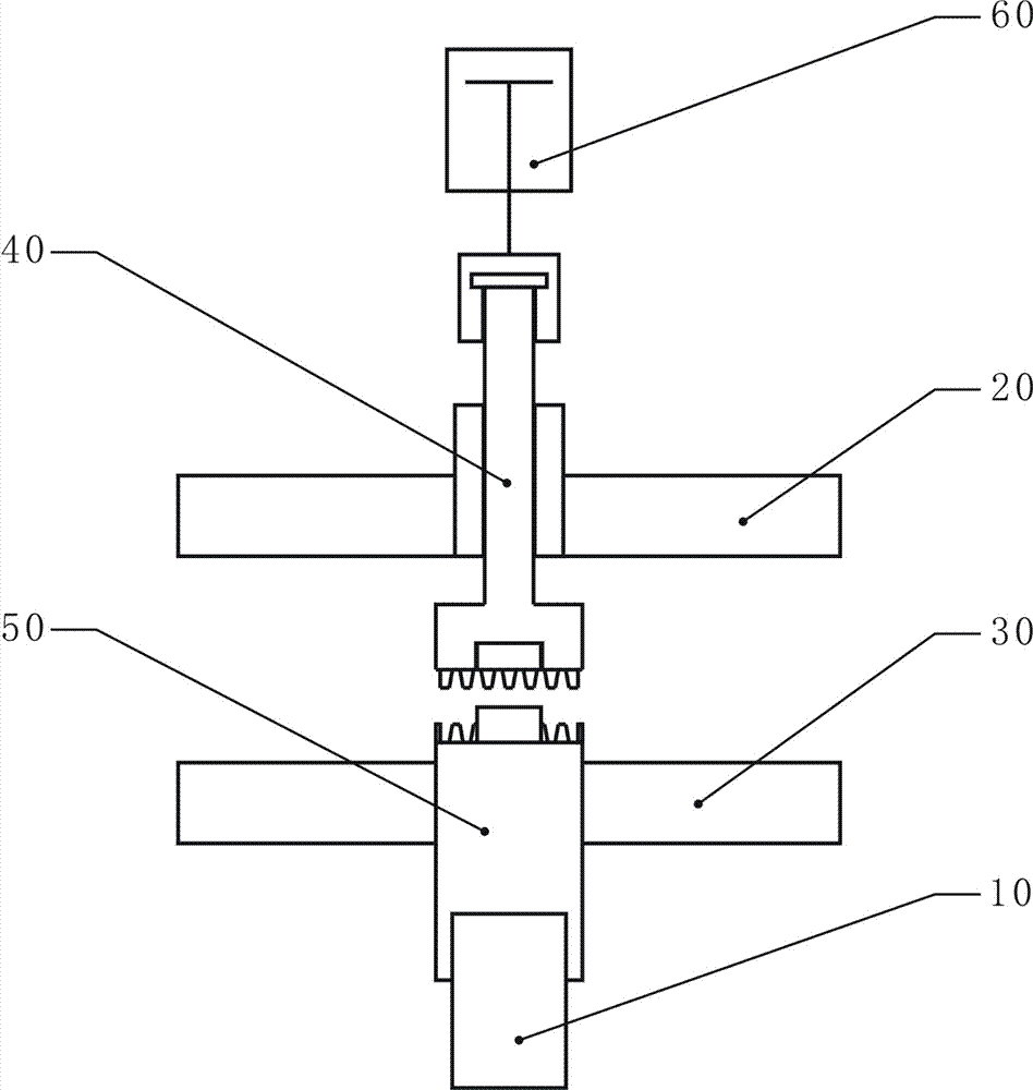
[0017] Such as figure 1 As shown, a double-layer tool magazine of the present invention includes a driving device 10 , an upper cutter head 20 , a lower cutter head 30 , an upper rotation center 40 , a lower rotation center 50 and a cylinder power device 60 . The lower rotation center 50 is connected with the driving device 10, and is driven to rotate by the driving device 10; the upper rotation center 40 is connected with the cylinder power device 60, and can be separated and matched with the lower rotation center 50 under the control of the cylinder power device 60; The disk 20 is fixedly installed on the upper rotation center 40 , and the lower cutter head 30 is fixedly installed on the lower rotation center 50 .

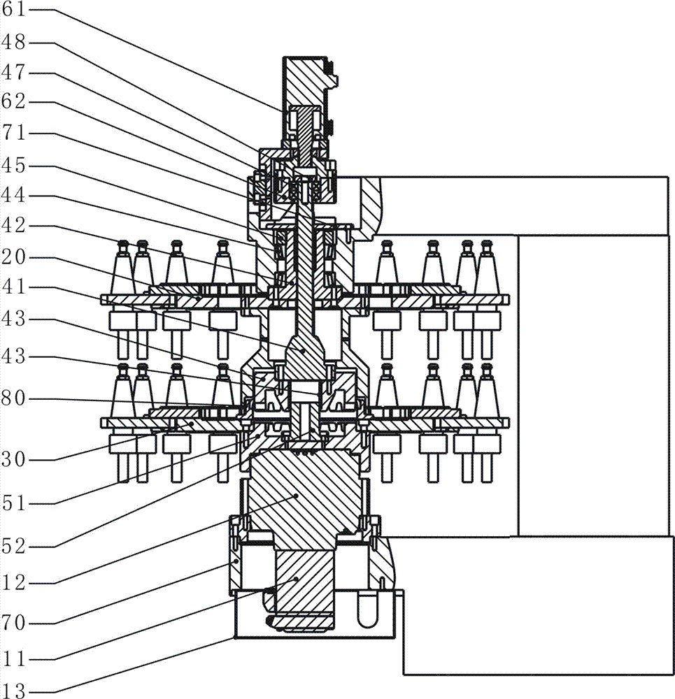
[0018] Such as figure 2 As shown, the driving device 10 includes a servo motor 11 and a reducer 12. The servo motor...


PUM


Abstract

The invention belongs to the technical field of numerical control equipment, in particular relates to a double-layer tool magazine. The double-layer tool magazine is comprised of a driving device, an upper cutter head, a lower cutter head, a clutch driving device, and a cylinder power device; the clutch driving device comprises an upper rotating center and a lower rotating center, wherein the lower rotating center is an active part, and the upper rotating center is a driven part; the upper rotating center is connected with the cylinder power device, and can realize separation and coordination with the lower rotating center under the control of the cylinder power device; the upper cutter head is fixedly arranged on the upper rotating center; the lower cutter head is fixedly arranged on the lower rotating center and is driven by the driving device to rotate; and the upper cutter head and the lower cutter head are both provided with a tool apron used for holding tools. The double-layer tool magazine is compact in structure, small in space occupation, convenient to processing and manufacturing, low in cost, fast in tool change, the number of tools on machine tools can be greatly increased under the premise of a small occupation area of the numerical control machine tool, and the double-layer tool magazine is applicable to all types of numerical control machine tools.

Description

technical field [0001] The invention belongs to the technical field of numerical control equipment, in particular to a double-layer tool magazine. Background technique [0002] With the development of CNC machining technology, the application fields of CNC machine tools continue to expand, and higher requirements are put forward for the processing capabilities of CNC machine tools. The processing requirements of multiple features of the workpiece require that the CNC machine tool must be able to accommodate a sufficient number of tools. However, for small and medium-sized machine tools with better finishing performance, due to the limited capacity of the tool magazine, they cannot meet the processing requirements for multiple features of the workpiece. [0003] At present, the common methods to increase the number of tools carried by the machine tool mainly include increasing the number of tool magazines and changing the type of tool magazines. Increasing the number of too...

Claims


Application Information

Patent Timeline
IPC IPC(8): B23Q3/155
CPCB23Q3/15506B23Q3/15526Y02P70/10B23Q3/15722Y10T483/115B23Q3/15539B23Q11/08
Inventor 王岱潘华峰崔师虎
Owner BEIJING JINGDIAO GRP CO LTD
Learn More