Birdcage coil for a magnetic resonance imaging system and tuning method thereof

A magnetic resonance imaging and birdcage technology, which is applied in the fields of magnetic resonance measurement, magnetic variable measurement, and measuring devices, etc., can solve the problem of difficulty in controlling the quality of birdcage coil product manufacturers, increased work difficulty of magnetic resonance imaging systems, and birdcage coil tuning Complex process and other issues, to achieve the effect of easy debugging, high reliability, and uniform current distribution

Pending Publication Date: 2017-07-25
SHENZHEN RF TECH
View PDF22 Cites 20 Cited by
  • Summary
  • Abstract
  • Description
  • Claims
  • Application Information

AI Technical Summary

Problems solved by technology

When the magnet is installed in the shielding room, due to the difference in materials and site environment, the resulting static magnetic field strength B 0 There are also certain differences, and the errors in the coil manufacturing process will also lead to certain differences
This requires that all the radio frequency coils matching the magnet need to adjust the resonant frequency accordingly. As mentioned above, the tuning process of the existing birdcage coil is complicated, which increases the difficulty of work for the on-site installers of the magnetic resonance imaging system, often making the birdcage The product quality of the cage coil has a hidden danger that the processing manufacturer is difficult to control

Method used


Image

  • Birdcage coil for a magnetic resonance imaging system and tuning method thereof
  • Birdcage coil for a magnetic resonance imaging system and tuning method thereof
  • Birdcage coil for a magnetic resonance imaging system and tuning method thereof

Examples


Embodiment Construction

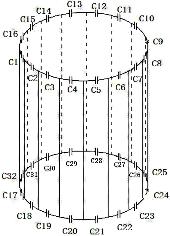
[0027] Common birdcage coil structures for MRI systems, such as figure 1 As shown, this conventional birdcage coil uses two parallel ring conductors, a plurality of linear conductors are connected between the two ring conductors, and multiple capacitors are assembled on the two ring conductors.

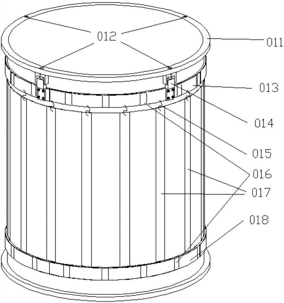
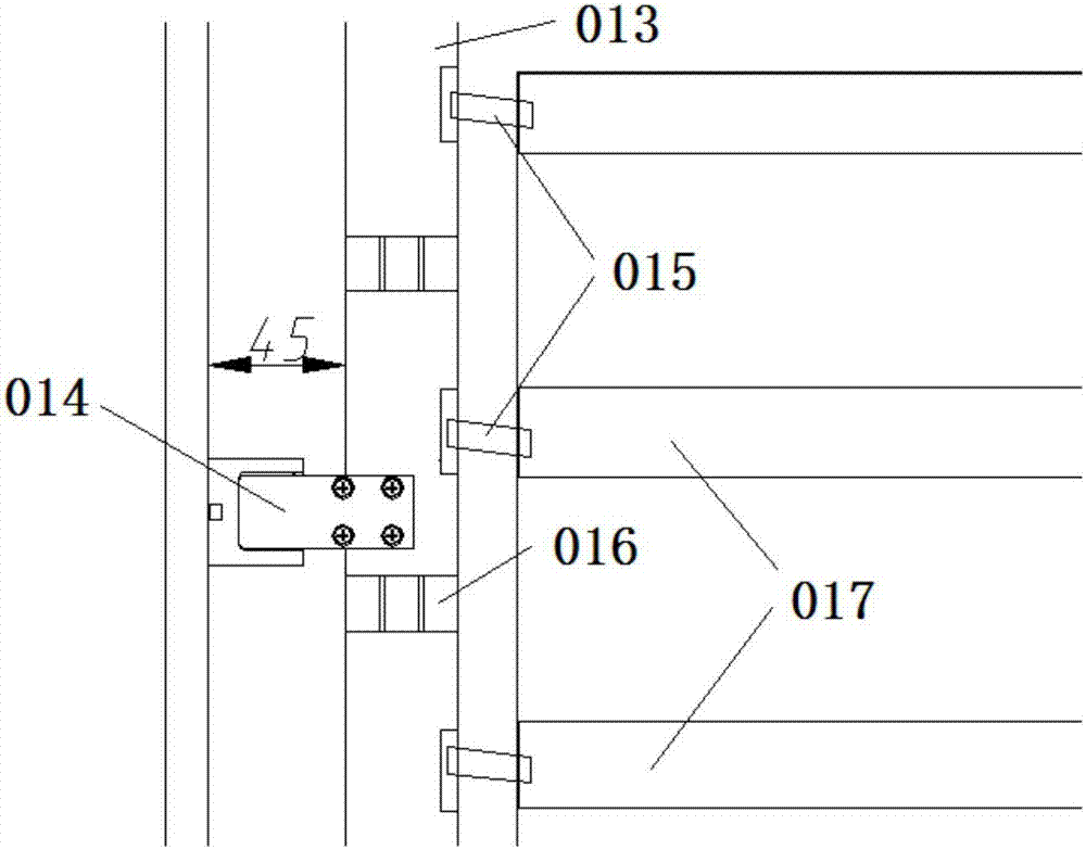
[0028] The invention completely replaces the rigid linear conductor in the traditional birdcage coil with a flexible linear conductor. That is, the linear conductor between the upper and lower ring conductors is flexible and bendable, so that the distance between the upper and lower ring conductors can be easily adjusted according to requirements at the installation site of the nuclear magnetic resonance system, thereby changing the resonance point of the birdcage coil, Adapt to the requirements of the static magnetic field strength of the magnet. In one embodiment, the deformation of the flexible and bendable linear conductor is limited by the packaging shell of the radio frequency ...


PUM


Abstract

The invention relates to a birdcage coil for a magnetic resonance imaging system and a tuning method thereof. The birdcage coil comprises an upper annular conductor, a lower annular conductor and a plurality of linear conductors which are distributed on a cylindrical surface, wherein the linear conductors are connected between the upper annular conductor and the lower annular conductor. A plurality of capacitors are connected in series in the upper annular conductor and the lower annular conductor. The whole or a part of the linear conductor is flexibly bendable and deformable. The distance between the upper annular conductor and the lower annular conductor is changed when the degree of bending deformation of the linear conductor is adjusted so that the resonant frequency of the birdcage coil is changed. The resonant frequency is adjusted by changing the position of a debugging ring. Thus, an expensive adjustable capacitor device is replaced so as to reduce the cost of the birdcage coil. The birdcage coil can be easily debugged at the installation site of the magnetic resonance system. The structure of the whole birdcage coil is adjusted synchronously and a large tuning range is achieved. The distribution of coil current and the uniformity of an RF magnetic field inside the coil are not influenced. The birdcage coil is stable in mechanical structure and can withstand high voltage.

Description

technical field [0001] The present invention relates to magnetic resonance imaging technology, in particular to the radio frequency transmitting and receiving technology in the magnetic resonance imaging system, specifically, the present invention relates to the birdcage coil used in the magnetic resonance imaging system and its tuning method. Background technique [0002] Magnetic resonance imaging technology has become one of the important tools for medical clinical diagnosis and research. It has the characteristics of non-invasiveness, no ionization, and no radiation. The radio frequency coil is an important component of the imaging system and plays a decisive role in the imaging quality. It directly affects the image signal-to-noise ratio. The magnetic resonance imaging system emits electromagnetic waves through the radio frequency transmitting coil to excite the human tissue, and the resonance signal is generated in the human tissue, which is received by the radio frequ...

Claims


Application Information

Patent Timeline
Patent Type & Authority Applications(China)
IPC IPC(8): G01R33/34
CPCG01R33/34076
Inventor 杨佳强
Owner SHENZHEN RF TECH
Why Eureka
Try Eureka