Supercharge Your Innovation With Domain-Expert AI Agents!

Coupling network, power amplifier device and communication terminal

A technology of coupling network and coupler, which is applied to parts of amplification devices, power amplifiers, amplifiers, etc., and can solve problems such as poor isolation

Inactive Publication Date: 2017-07-25
ZTE CORP
View PDF0 Cites 0 Cited by
  • Summary
  • Abstract
  • Description
  • Claims
  • Application Information

AI Technical Summary

Problems solved by technology

[0006] The invention provides a coupling network, a power amplifier and a communication terminal to solve the problem of poor isolation of the existing typical coupling network when applied to a variable output impedance framework

Method used


Image

  • Coupling network, power amplifier device and communication terminal
  • Coupling network, power amplifier device and communication terminal
  • Coupling network, power amplifier device and communication terminal

Examples


no. 1 example

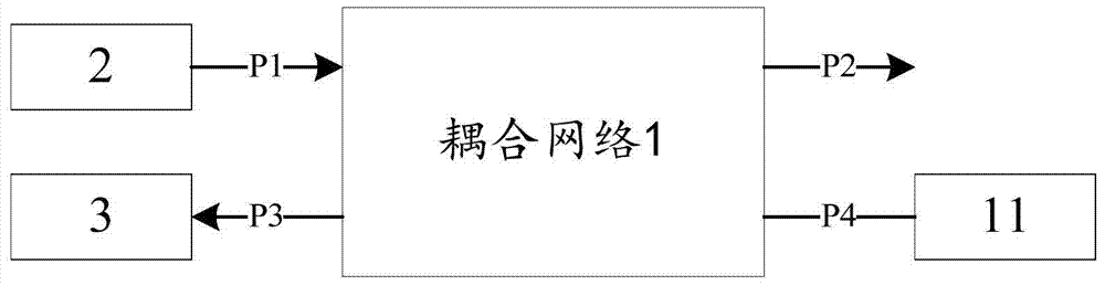
[0030] figure 2 The schematic structural diagram of the coupling network provided for the first embodiment of the present invention is represented by figure 2 It can be seen that, in this embodiment, the coupling network 1 provided by the present invention includes: at least four ports (p1, p2, p3 and p4) and a non-reciprocal coupler matching circuit 11, wherein at least one port p1 is a variable impedance port , the impedance variable port is used to connect the impedance variable circuit 2, the coupler isolation port p4 corresponding to the impedance variable port p1 is a non-reciprocal coupler matching port, and the non-reciprocal coupler matching port p4 belongs to the feedback control link The feedback port p3 is used to connect the digital predistortion circuit 3; the non-reciprocal coupler matching port p4 is connected to the non-reciprocal coupler matching circuit 11, and the non-reciprocal coupler matching circuit 11 is used to reverse the reflected interference sig...

no. 2 example

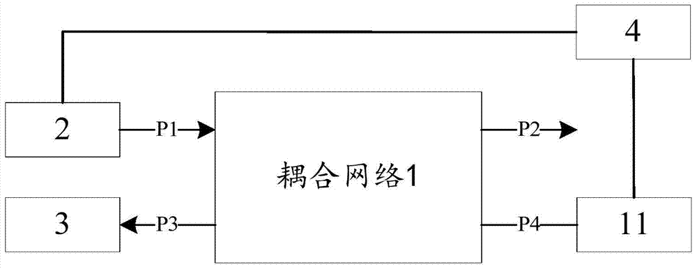
[0037] image 3 The structural schematic diagram of the power amplifier device provided for the second embodiment of the present invention is represented by image 3 It can be seen that, in this embodiment, the power amplifier device provided by the present invention includes:

[0038] The impedance variable circuit 2, the digital predistortion circuit 3 and the coupling network 1 provided by the present invention transmit signals through the impedance variable circuit 2, the impedance variable port of the coupling network 1 is connected to the impedance variable circuit 2, and the digital predistortion circuit 3 is connected to The non-reciprocal coupler matches the feedback port of the feedback control link to which the port belongs, obtains and utilizes the feedback signal to correct the operation of the variable impedance circuit 2 .

[0039] In some embodiments, the variable impedance circuit 2 in the above embodiments includes a Doherty circuit.

[0040] In some embodi...


PUM


Abstract

The invention provides a coupling network, a power amplifier device and a communication terminal. The coupling network comprises at least four ports and a non-reciprocal coupler matching circuit, wherein at least one port is an impedance variable port, the impedance variable port is used to connect an impedance variable circuit, a coupler isolation port corresponding to the impedance variable port is a non-reciprocal coupler matching port, and a feedback port of a feedback control circuit to which the non-reciprocal coupler matching port belongs is used to connect a digital predistortion circuit; and the non-reciprocal coupler matching port is connected with the non-reciprocal coupler matching circuit, and the non-reciprocal coupler matching circuit enables reflection interference signals and emission interference signals to perform reverse superposition. Through the implementation of the invention, the non-reciprocal coupler matching circuit ensures that the reflection interference signals and the emission interference signals are in reverse superposition during use, the radio frequency energy is converted into the heat energy for dissipation, and the interference of coupling signals can be reduced to a maximum extent without affecting the normal coupling signals.

Description

technical field [0001] The invention relates to the field of radio frequency power amplifier communication, in particular to a coupling network, a power amplifier device and a communication terminal. Background technique [0002] Doherty power amplifier is the most widely used high-efficiency power amplifier technology in wireless communication systems. It was invented in 1936 by an American electronic engineer named William H. Doherty. But over the next three decades or so, attention shifted. Until the end of the 1960s, with the development of communication technology, especially satellite communication, the efficiency and linearity of power amplifiers were raised again in a new historical occasion, and the Doherty amplifier was excavated again, widely used in communication in the 1970s and broadcasting systems. Today, the combined application of Doherty power amplifiers and DPD (Digital Pre-distortion) technology has become the mainstream architecture of high-efficiency ...

Claims


Application Information

Patent Timeline
IPC IPC(8): H04L25/02H03F1/07H03F1/32H03F1/56H03F3/24
CPCH04L25/02H03F1/07H03F1/32H03F1/56H03F3/24H04L25/0278H03F1/3241
Inventor 杨云博
Owner ZTE CORP
Features
  • R&D
  • Intellectual Property
  • Life Sciences
  • Materials
  • Tech Scout
  • Unparalleled Data Quality
  • Higher Quality Content
  • 60% Fewer Hallucinations
Learn More