Water supply device for automatic feed feeder using potential difference between two potential sensing needles

A technology of supplying device and potential difference, which is applied in the direction of animal drinking device, animal feeding device, non-electric variable control, etc., can solve the problem of water not flowing out.

Inactive Publication Date: 2020-11-10
金基柱
View PDF10 Cites 0 Cited by
  • Summary
  • Abstract
  • Description
  • Claims
  • Application Information

AI Technical Summary

Problems solved by technology

[0006] However, the disadvantage of the conventional device as described above is that if water sticks to the feed liquid sensing rod, it is judged that there is water, so even if it is in a state of water shortage, water cannot flow out, so that it cannot supply an appropriate amount of water to pigs.

Method used


Image

  • Water supply device for automatic feed feeder using potential difference between two potential sensing needles
  • Water supply device for automatic feed feeder using potential difference between two potential sensing needles
  • Water supply device for automatic feed feeder using potential difference between two potential sensing needles

Examples


Embodiment Construction

[0016] In the present invention, the water supply device of the automatic feed feeder which utilizes the potential difference of two potential sensing needles includes: a feed substrate 30 containing feed or water so that the pigs can eat it; a feed supply part, which supplies feed to the feeding substrate 30; a water supply part, which supplies water to the feeding substrate 30;

[0017] It is characterized in that, the water supply part includes: a water supply pipe, which is provided to obtain the supply of water to be supplied to the supply substrate 30; and a solenoid valve 81, which is provided in a part of the water supply pipe, according to the control part. The voltage signal is switched on and off, so as to be able to control whether the moving water moves or not; the upper potential sensing needle 111 is arranged on the feeding substrate 30 in a form of a certain height isolation, and senses the water level of the upper water , so that the water does not overflow; t...


PUM


Abstract

The present invention relates to a water supplying apparatus in an automatic feeding machine using a 
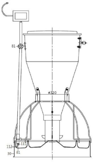
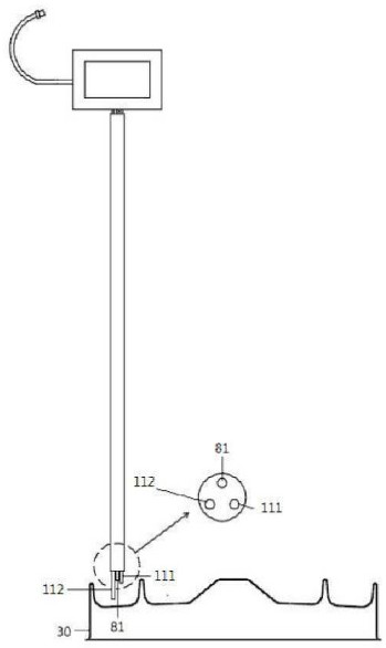
potential difference of two potentiometric sensors. The water supplying apparatus comprises a feeding base plate (30) for storing feed or water so that pigs can eat the same; a feed supply part supplying feed to the feeding base plate (30); and a water supplying part supplying water to the feeding base plate (30). The water supplying part includes a water supplying pipe (80) configured to obtain water to be supplied to the feeding base plate (30); an electromagnetic valve (81) disposed at a part of the water supplying pipe (80) and being closed or opened according to voltage signals of a controller so as to control whether moving water is moving or not; an upper potentiometric sensor (111) disposed above the feeding base plate (30) in a separated manner at a certain height, and sensing the water level of upper water so as to prevent overflow; a lower potentiometric sensor (112) disposed lower than the upper potentiometric sensor (111) and performing sensing operation in a manner of preventing 
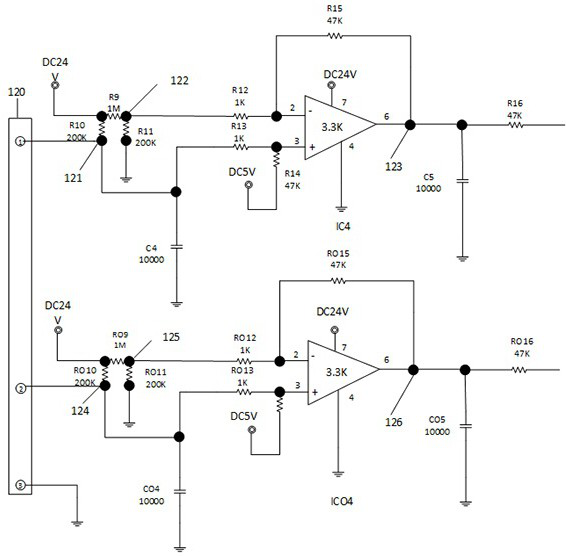
water level reduction; a circuit part (120) generating a needed measured value based on voltages sensed by the upper potentiometric sensor (111) and the lower potentiometric sensor (112); and a controller controlling the electromagnetic valve (81) based on the measured value of the circuit part (120). The circuit part (120) includes an upper probe voltage input part (121) connected to the upper potentiometric sensor (111), an upper reference voltage part (122) independent of the voltage of the upper probe voltage input part (121) and always having a same reference voltage, an upper voltage detection part (123) changing the voltage under a situation that water and the upper potentiometric sensor (111) are in contact and a situation that no water is in contact with the upper potentiometric sensor (111), a lower probe voltage input part (124) connected to the lower potentiometric sensor (112), a lower reference voltage part (125) independent of the voltage of the lower probe voltage input part (124) and always having a same reference voltage, and a lower voltage detection part (126) changing the voltage under a situation that water and the lower potentiometric sensor (112) are in contact and a situation that no water is in contact with the lower potentiometric sensor (112). Significant effects of the water supplying apparatus are that a problem that water supply stopping caused by the controller mistakes a small amount of water adhered to a side surface for presence of water, instead of full water filling, is overcome, accordingly, moist and a small amount of water having a waterdrop size adhered to surfaces of the two potentiometric sensors are ignored, no response is made for the small amount of water, and a situation that pigs cannot drink water due to no water discharge is prevented; the upper potentiometric sensor is disposed above the feeding base plate at a certain height and the lower potentiometric sensor is disposed lower than the upper potentiometric sensor; the controller determines the voltage of a voltage sensing plate outputted by a potential difference through the two potentiometric sensors, and controls the electromagnetic valve based on a determined resistance; in particular, pigs in summer cannot bear scorching heat so that severe playing with water is common, and waggling water waves allow the electromagnetic valve to be in a closed state so that water does not flow out and playing is prevented even if pigs like playing with water; water is supplied to reach a certain level by controlling water, thereby preventing waste of water; and hygienic and efficient maintenance is possible.

Description

technical field [0001] The invention relates to a water supply device for an automatic feed feeder that utilizes the potential difference of two potential sensing needles, and more particularly, relates to a water supply device for an automatic feed feeder that utilizes the potential difference between two potential sensing needles The water supply device of the automatic feed feeder using the potential difference between the two potential sensing needles uses the two potential sensing needles to sense that the solenoid valve automatically does not exist when the control unit senses that there is no water contacting the lower potential sensing needle. Open, if the water is filled to the feeding substrate, the control unit judges that the water touches the upper potential sensing needle, and closes the solenoid valve. If only a certain water level is supplied by the control unit according to the potential difference, the water loss is prevented. Avoid the water being left for a...

Claims


Application Information

Patent Timeline
Patent Type & Authority Patents(China)
IPC IPC(8): A01K5/02A01K7/02G05D9/12
CPCA01K5/02A01K7/02G05D9/12
Inventor 金基柱
Owner 金基柱
Why Eureka
Try Eureka