Multimodal imaging system and imaging method thereof

A multi-modal imaging and imaging probe technology, applied in the field of biomedical imaging, can solve problems such as time-consuming, low detection efficiency of detection samples, and inability to measure and analyze the structure, distribution and composition of biological tissues

Active Publication Date: 2021-02-09
SHENZHEN INST OF ADVANCED TECH CHINESE ACAD OF SCI
View PDF6 Cites 0 Cited by
  • Summary
  • Abstract
  • Description
  • Claims
  • Application Information

AI Technical Summary

Problems solved by technology

[0003] However, the photoacoustic-fluorescence imaging system in the prior art has some shortcomings, for example, it can only detect the photoacoustic-fluorescence signal under a certain wavelength of the laser signal, so that the accuracy of the detection result is not high, or it can be Detect photoacoustic-fluorescence signals under laser signals of different wavelengths, but it takes a lot of time to switch between different wavelengths, which causes the detection process to take too long and reduces the detection efficiency when more samples are detected
The photoacoustic-fluorescence imaging system in the prior art cannot perform dynamic real-time measurement and analysis of information such as the structure, distribution and composition of biological tissues

Method used


Image

  • Multimodal imaging system and imaging method thereof
  • Multimodal imaging system and imaging method thereof
  • Multimodal imaging system and imaging method thereof

Examples


Embodiment Construction

[0032] The following will clearly and completely describe the technical solutions of the embodiments of the present invention with reference to the drawings in the embodiments of the present invention.

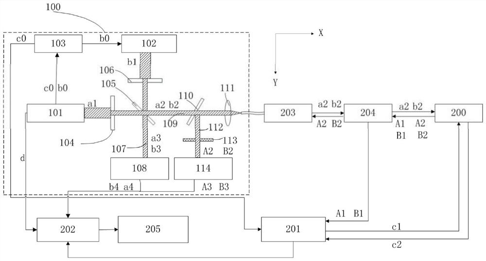
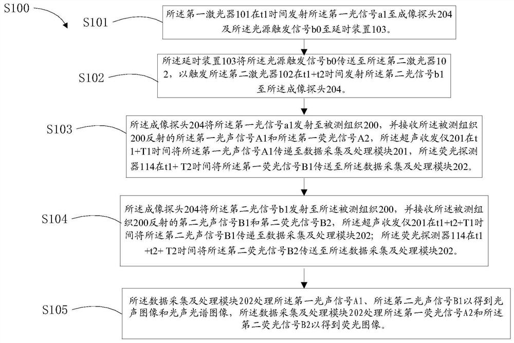
[0033] see figure 1 , figure 1 It is a multimodal imaging system provided by an embodiment of the present invention, which is used to collect physiological parameters such as the tissue structure and composition of the measured tissue 200. The multimodal imaging system includes an optical module 100, a motion control module 203, an imaging probe 204 , an ultrasonic transceiver 201 , a data acquisition and processing module 202 , and a display module 205 .

[0034] The optical module 100 is used to couple optical signals of different wavelengths into the optical fiber, and the optical fiber transmits the optical signal to the motion control module 203 and the imaging probe 204, and transmits the optical signal to the surface of the measured tissue 200 through the imaging probe...


PUM


Abstract

The invention provides a multimode imaging system and an imaging method thereof. The multimode imaging system comprises a first laser device, a second laser device, a delay device, an imaging probe, an ultrasonic transceiving instrument, a fluorescent detector and a data acquisition and processing module. The first laser device generates a first light signal and a light source triggering signal, and the light source triggering signal is transmitted to the second laser device through the delay device to generate a second light signal. The first light signal and the second light signal are emitted to detected tissue through the imaging probe, and a first photoacoustic signal, a first fluorescent signal, a second photoacoustic signal and a second fluorescent signal are excited separately. The first laser device further generates an ultrasonic triggering signal, and the ultrasonic triggering signal is transmitted to the ultrasonic transceiving instrument through the delay device to generate a second ultrasonic signal. The signals are all received by the imaging probe and transmitted to the data acquisition and processing module to obtain image information. The multimode imaging system can simultaneously obtain photoacoustic, ultrasonic, fluorescent and photoacoustic spectrum imaging information of the detected tissue.

Description

technical field [0001] The invention relates to the technical field of biomedical imaging, in particular to a multimodal imaging system and an imaging method thereof. Background technique [0002] Photoacoustic imaging technology is a non-invasive biomedical imaging technology that combines the advantages of optical and ultrasonic imaging. It has the advantages of large depth and high resolution imaging for obtaining information such as the morphology, structure and distribution of lesions. However, this imaging technology mainly focuses on structural For functional imaging, it is difficult to obtain functional quantitative data, and it is also impossible to obtain the content of a specific component in the tissue. Fluorescence imaging technology can detect the composition of different molecules through fluorescent endoscopic probes, and can also indicate the status of tumors or lesions such as atherosclerotic plaques in blood vessels. However, fluorescent endoscopic probes...

Claims


Application Information

Patent Timeline
Patent Type & Authority Patents(China)
IPC IPC(8): A61B5/00A61B8/00
CPCA61B5/0035A61B5/0071A61B5/0075A61B5/0095A61B8/44A61B8/5207
Inventor 宋亮燕康龚小竞林日强刘成波刘筱阳
Owner SHENZHEN INST OF ADVANCED TECH CHINESE ACAD OF SCI
Why Eureka
Try Eureka