Structure and method for coaxial protection gas blowing of laser welding machine

A laser welding machine and shielding gas technology, applied in laser welding equipment, welding equipment, metal processing equipment, etc., can solve the change of the control effect of plasma outside the hole to suppress blow-off, affect the formation of weld penetration, and the welding process is unstable. and other problems, to achieve the effect of not easy to be oxidized, improve quality, and even out gas.

Active Publication Date: 2017-07-28
WUHAN YIFI LASER EQUIP CO LTD
View PDF4 Cites 9 Cited by
  • Summary
  • Abstract
  • Description
  • Claims
  • Application Information

AI Technical Summary

Problems solved by technology

[0002] Laser welding is to use high-energy laser pulses to locally heat the material in a small area. The energy of the laser radiation diffuses to the inside of the material through heat conduction, and the material is melted to form a specific molten pool to achieve the purpose of welding. In welding, it is necessary to carry out Blowing protective gas, the function of protective gas is, 1. Protect the focusing lens from metal vapor pollution and sputtering of liquid droplets. The protective gas can protect the laser welding machine focusing lens from metal vapor pollution and sputtering of liquid droplets, especially During high-power welding, because the ejecta becomes very powerful, it is more necessary to protect the lens at this time. Second, the shielding gas is very effective in dispelling the plasma shielding generated by high-power laser welding. Third, the shielding gas can make the workpiece in the Avoid oxidation during the welding process. In the prior art, a side blowing device is used to blow the shielding gas for laser welding, that is, the shielding gas inlet pipe enters from the side of the laser coaxial sleeve, and the side of the existing laser welding shielding gas The blowing device moves together with the welding head, and the blowing direction of the shielding gas remains unchanged relative to the welding head. When the welding track is a straight line, the blowing direction of the shielding gas remains unchanged relative to the welding track. For laser welding with complex irregular curve tracks, using the existing laser welding shielding gas side blowing device, it often occurs that the direction of blowing shielding gas is changed relative to the welding track, the weld seam is easily oxidized, and the blowing of the plasma outside the hole is suppressed. The change of the dispersion control effect will cause the welding process to be unstable, affect the penetration depth of the weld, the formation of pores, etc., which is not conducive to the needs of welding, resulting in a decrease in the performance of the weld; and cause turbulence of the air flow on the welding surface, forming splashes, polluting the lens, etc. Moreover, the existing side blowing device for laser welding shielding gas takes in air from the side in a single direction, which is likely to cause waste of shielding gas and increase the amount of shielding gas

Method used


Image

  • Structure and method for coaxial protection gas blowing of laser welding machine
  • Structure and method for coaxial protection gas blowing of laser welding machine
  • Structure and method for coaxial protection gas blowing of laser welding machine

Examples


Embodiment Construction

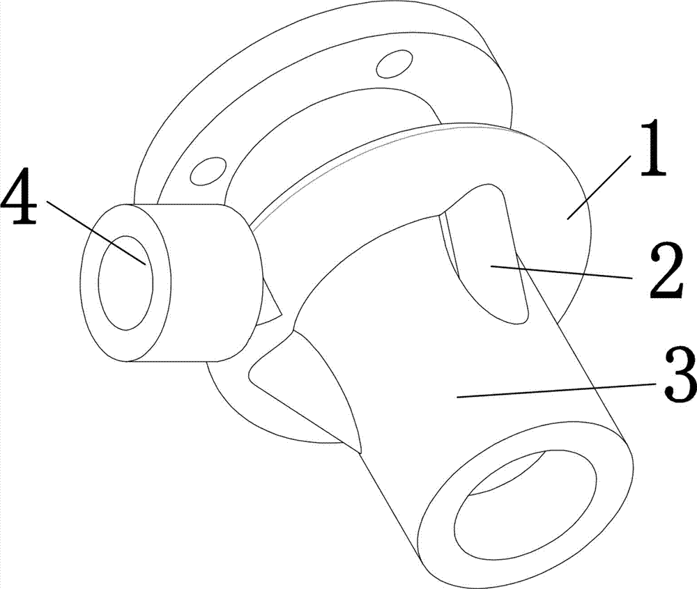
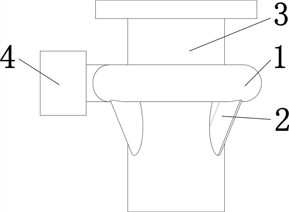
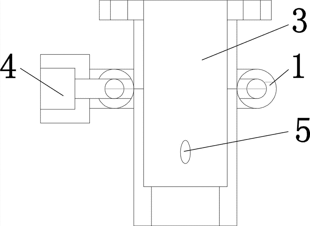
[0021] Combine below Figure 1-5 The present invention is further described, but the protection scope of the present invention is not limited to the content.

[0022] Wherein the same components are denoted by the same reference numerals. It should be noted that the words "front", "rear", "left", "right", "upper" and "lower" used in the following description refer to the directions in the drawings, and the words "inner" and "outer "respectively refer to directions toward or away from the geometric center of a specific component, and the drawings are all in a very simplified form and use inaccurate ratios, which are only used to facilitate and clearly assist the purpose of illustrating the embodiments of the present invention.

[0023] For the sake of clarity, not all features of an actual embodiment are described. In the following description, well-known functions and constructions are not described in detail since they would obscure the invention with unnecessary detail and ...


PUM


Abstract

The invention discloses a structure for coaxial protection gas blowing of a laser welding machine. The structure comprises a surrounding coil pipe and protection gas inlet pipes. The surrounding coil pipe is wound around the outer side of a laser coaxial sleeve. One end of the surrounding coil pipe is connected with a protection gas inlet. The three protection gas inlet pipes are arranged and arranged at the lower end of the surrounding coil pipe to connect the surrounding coil pipe with the laser coaxial sleeve. The included angle between each protection gas inlet pipe and the laser coaxial sleeve is an acute angle. The position, connected with the protection gas inlet pipes, of the laser coaxial sleeve is provided with a coaxial sleeve protection gas inlet. The structure has the beneficial effects that through the arrangement of the surrounding coil pipe and the protection gas inlet pipes, protection gas is evenly distributed on the periphery of a welding head, gas outflow is even, a welding line is not prone to oxidization during welding, the welding process is stable, the welding line is smooth, the quality is enhanced, and welding gas holes are avoided; and compared with side-face single-direction gas inflow, waste of the protection gas is not prone to being caused, the usage amount of the protection gas is reduced, splashing objects entering the coaxial sleeve during welding can be blown away, and lens damage is prevented.

Description

technical field [0001] The invention relates to a structure and method for blowing protective gas, in particular to a structure and method for coaxially blowing protective gas for a laser welding machine. Background technique [0002] Laser welding is to use high-energy laser pulses to locally heat the material in a small area. The energy of the laser radiation diffuses to the inside of the material through heat conduction, and the material is melted to form a specific molten pool to achieve the purpose of welding. In welding, it is necessary to carry out Blowing protective gas, the function of protective gas is, 1. Protect the focusing lens from metal vapor pollution and sputtering of liquid droplets. The protective gas can protect the laser welding machine focusing lens from metal vapor pollution and sputtering of liquid droplets, especially During high-power welding, because the ejecta becomes very powerful, it is more necessary to protect the lens at this time. Second, t...

Claims


Application Information

Patent Timeline
Patent Type & Authority Applications(China)
IPC IPC(8): B23K26/142B23K26/14
CPCB23K26/14B23K26/142
Inventor 冯臣相
Owner WUHAN YIFI LASER EQUIP CO LTD
Why Eureka
Try Eureka