Cutting device for post processing of handmade soap

A cutting device and handmade soap technology, applied in the direction of cutting soap, etc., can solve the problem of low cutting efficiency, achieve high cutting speed, large cutting volume, and improve cutting efficiency

Inactive Publication Date: 2017-07-28
橄享成都科技有限责任公司
View PDF6 Cites 1 Cited by
  • Summary
  • Abstract
  • Description
  • Claims
  • Application Information

AI Technical Summary

Problems solved by technology

[0004] The technical problem to be solved by the present invention is that under the condition of low cost, the cutting efficiency of traditional hand-cut rectangular parallelepiped soap with long sides is low. efficiency problem

Method used


Image

  • Cutting device for post processing of handmade soap

Examples


Embodiment 1

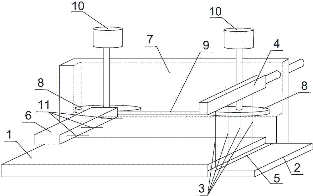
[0022] Such as figure 1 As shown, the cutting device for handmade soap post-processing of the present invention includes a horizontally placed cuboid workbench 1, and the side of the workbench 1 with width and height as sides is connected with a support plate 2 in parallel, and the support plate 2 There are at least three cutting wires 3 connected above, and all cutting wires 3 are equally spaced and parallel distributed along the width direction of the workbench 1, all cutting wires 3 are perpendicular to the support plate 2, and the upper ends of the cutting wires 3 are connected to the fixed block 4 , the lower ends of the cutting wires 3 are all connected to the slide plate 5 sliding along the width direction of the workbench 1, the slide plate 5 is slidably connected with the support plate 2, a push plate 6 is arranged above the workbench 1, and the push plate 6 is located on the working table The other side of the table 1 is opposite to the cutting wire 3, and the side s...

Embodiment 2

[0025] Based on Embodiment 1, the side of the workbench 1 with the length and height as the sides is connected and fixed with a panel 7, the height of the panel 7 is perpendicular to the table top of the workbench 1, two transmission wheels 8 are installed on the panel 7, and the two Two transmission wheels 8 are respectively located on both sides of the panel 7, and a conveyor belt 9 is sleeved between the two transmission wheels 8, and one end of the push plate 6 is fixed on the transmission surface of the conveyor belt 9 on one side of the workbench 1, and the conveyor belt 9 Convey along the long side of workbench 1. A motor 10 that controls the rotation of the transmission wheel 8 is connected above each transmission wheel 8 , and the motor 10 is located above the panel 7 .

[0026] The panel plays a role in supporting the transmission wheel. The transmission direction of the two transmission wheels is the same. The transmission wheel rotates and then conveys the conveyor...


PUM


Abstract

The invention discloses a cutting device for post processing of handmade soap. The cutting device comprises a cuboid workbench placed horizontally, wherein the workbench is connected with a supporting plate parallel to a side face using width and height as sides; the upper part of the supporting plate are connected with at least three cutting wires; the cutting wires are distributed in parallel at equal intervals along the width direction of the workbench; all the cutting wires are perpendicular to the supporting plate respectively; the upper ends of the cutting wires are respectively connected onto a fixed block; the lower ends of the cutting wires are respectively connected onto a sliding plate sliding along the width direction of the width direction; the sliding plate is connected with the supporting plate in a sliding manner; a pushing plate is arranged above the workbench; the pushing plate is positioned on the other side of the workbench and is opposite to the cutting wires; and a fixed device for fixing the handmade soap is arranged on the side face, facing the cutting wires, of the pushing plate. The handmade soap is pushed along the long side of the workbench, so that the handmade soap with long side is prevented from being collided or broken by manual operation, the cutting quality of the handmade soap is improved, and then the cutting efficiency of the handmade soap is improved.

Description

technical field [0001] The invention relates to a cutting machine, in particular to a cutting device for post-processing of handmade soap. Background technique [0002] Handmade soap is soap made artificially using natural oils and lye. Basically, it is the result of the saponification reaction of oil and lye, and can be used for washing and cleaning after solidification and aging procedures. Commonly used fats include olive oil, palm oil, and coconut oil. Lye is usually an aqueous solution of sodium hydroxide or potassium hydroxide. Handmade soap can also add various additives according to personal preferences and purposes, such as milk, breast milk, soy milk, essential oils, essences, flowers and herbs, Chinese medicinal materials, bamboo charcoal powder, preservatives, dyes, etc. [0003] The factory produces large-sized overall handmade soap by filling the mold, and then cuts the handmade soap with a knife to the target size; at present, for the low cost and high inco...

Claims


Application Information

Patent Timeline
Patent Type & Authority Applications(China)
IPC IPC(8): C11D13/22
CPCC11D13/22
Inventor 黄程
Owner 橄享成都科技有限责任公司
Why Eureka
Try Eureka